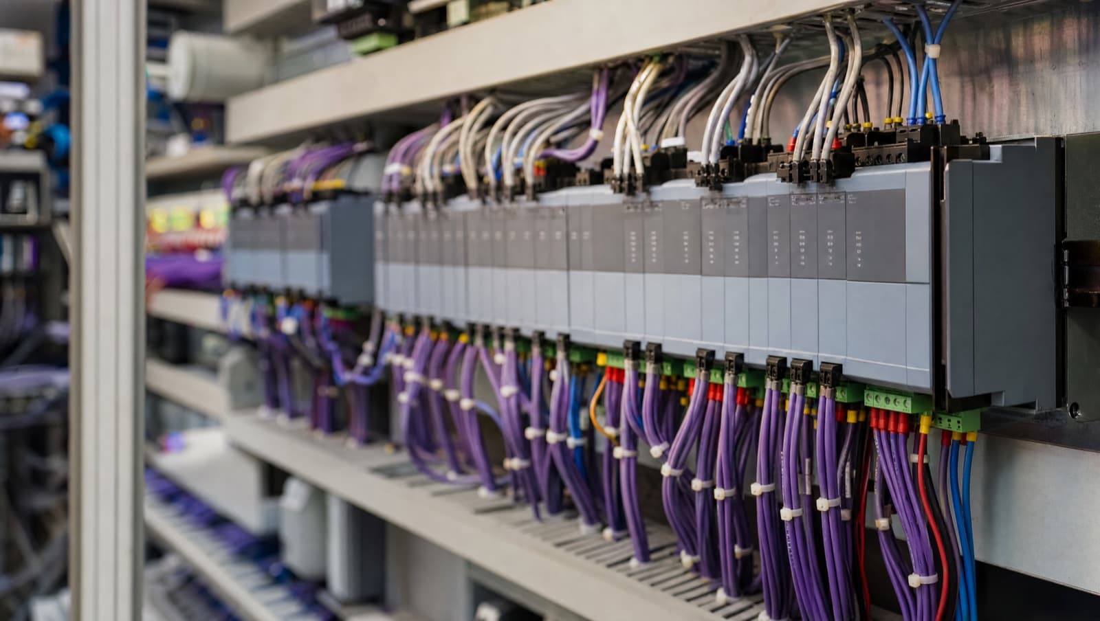

An end-of-line resistor does one of two jobs depending on where it is fitted: on an RS-485 data network such as BACnet MS/TP or Modbus RTU it terminates the cable to match its characteristic impedance and stop signal reflections, and on a supervised alarm or fire circuit it lets the panel measure loop resistance so it can tell a healthy circuit, a triggered device and a cut cable apart. It never does both jobs on the same circuit — which job it is doing, and therefore what value it should be, depends entirely on the application.
Use end-of-line resistors wherever a BMS needs a clean signal or supervised circuit: a 120Ω resistor at both ends of a BACnet MS/TP (RS-485) trunk to stop signal reflections, a pull-up resistor across a VAV controller's analog feedback to spot a cut cable, and a 4.7kΩ or 10kΩ resistor on supervised alarm and fire inputs to detect faults.
What is an end-of-line resistor?
An end-of-line resistor is a passive resistor fitted at the far end of a cable run so that the equipment at the other end sees a known, predictable electrical load. You will also see it called an EOL resistor, an EOLR, a termination resistor or a line monitoring resistor — on site those names get used interchangeably, but they describe two genuinely different jobs, and confusing the two is where most of the trouble starts.
The first job is signal termination. On a data network like RS-485 the resistor matches the characteristic impedance of the cable, absorbing the signal at the end of the run instead of letting it bounce back down the pair and collide with the next transmission. The second job is circuit supervision. On an alarm or fire circuit the resistor is not there for signal quality at all — it is there so the panel can measure the resistance of the loop and tell the difference between a healthy circuit, a triggered device and a cut cable.
The practical consequence is that the value matters, and it is decided by which job you are doing. A 120Ω resistor on a supervised fire circuit and a 4.7kΩ resistor across an RS-485 pair are both wrong, and both will look like a "wiring fault" to whoever inherits the building.
What resistance value should an end-of-line resistor be?
The value comes from the application, not from habit. Signal termination values are set by the cable's characteristic impedance and are effectively fixed; supervision values are set by the panel manufacturer and vary. These are the values you will meet in a commercial building:
| Application | Typical value | Where it goes | Job it does |
|---|---|---|---|
| BACnet MS/TP (RS-485) | 120Ω | First and last device on the trunk | Signal termination |
| Modbus RTU (RS-485) | 120Ω | Both physical ends of the segment | Signal termination |
| Modbus RTU polarization | Pull-up/pull-down pair, commonly ~650Ω | One designated point on the bus only | Holds the idle line in a defined state |
| VAV analog damper feedback | 10kΩ | Across the controller's analog input | Broken-cable detection |
| Supervised alarm / fire zone | 4.7kΩ or 10kΩ — check the panel | Last device on the zone | Circuit supervision |
| BACnet/IP over Ethernet | None | — | Handled by the switch |
Two rules survive every job. On RS-485 the 120Ω figure is not a preference — ASHRAE 135 specifies the RS-485 physical layer for MS/TP, and Trend's own IQ4NC data sheet calls for screened twisted-pair with a characteristic impedance between 100 and 130 ohms to match it. On supervised circuits there is no universal value at all: 4.7kΩ and 10kΩ are the common ones, but the panel data sheet is the only authority, and fitting the wrong value will put the panel into fault from the moment it is energised.
Why do BACnet MS/TP networks need 120Ω termination?
BACnet MS/TP runs over twisted-pair RS-485 cabling and needs proper termination at both ends of the network trunk. ASHRAE 135 — the BACnet standard — specifies that MS/TP networks use the RS-485 physical layer with a characteristic impedance of 120 ohms. The EOL termination resistors at both ends of the bus match this impedance, preventing the signal reflections that cause communication errors and dropped devices:
- Standard Termination Value: 120Ω resistor.
- Installation Location: First and last devices on the trunk cable.
- Why It's Needed: Prevents signal reflections that cause communication errors, especially in longer cable runs (>50 meters).
Example: In a building with a BACnet MS/TP trunk connecting 15 VAV controllers across three floors, a 120Ω termination resistor is installed at the first controller (near the IQ412 controller) and at the last controller on the opposite end of the network.
Get a Free BMS Survey
We'll assess your controls and provide a detailed quotation with energy savings estimates.
Does Modbus RTU need end-of-line resistors?
Yes — and for the same physical reason as BACnet MS/TP, because both ride on RS-485. Modbus RTU turns up constantly in commercial buildings on the equipment the BMS has to talk to rather than the BMS itself: energy meters, booster sets, inverters, chillers and packaged plant with their own controllers. The Modbus Organization's Modbus over Serial Line Specification and Implementation Guide V1.02 calls for 120Ω line termination at both ends of the trunk, matching the cable impedance exactly as MS/TP does.
Modbus differs from MS/TP in one respect worth knowing, because it explains a fault that otherwise makes no sense. Termination and polarization are separate jobs and they do not go in the same places. Termination is 120Ω at each of the two physical ends of the segment. Polarization — a pull-up and pull-down pair, commonly quoted around 650Ω — holds the line in a defined state when no device is transmitting, and the specification places it at a single designated point on the bus, typically the master or the equipment providing it, not at both ends and not on every device. Without bias the idle bus floats, receivers see noise as start bits, and you get a network that polls perfectly on a short bench test and then throws random CRC errors once it is installed in a plant room next to inverter drives. Most modern gateways provide switchable bias on board; on older kit it is a pair of resistors somebody has to fit.
In practice, if a Modbus RTU trunk is dropping devices intermittently, check termination and bias together before you start suspecting addresses or baud rates. For the wider comparison of where each protocol belongs on a building, see our guide to BACnet vs Modbus in BMS installations.
How long can an RS-485 BMS cable run be?
RS-485 — the physical layer used by BACnet MS/TP and Modbus RTU — is defined in BS EN 61158 as part of the fieldbus standard family. Its specification allows cable runs of up to 1,200 metres at 9,600 baud, but real-world BMS installations rarely achieve this without degraded signal integrity unless cable selection, termination, and shielding are all correctly implemented.
Why do VAV controllers use resistors on damper feedback?
Many Variable Air Volume (VAV) controllers use analog inputs (0-10V or 4-20mA) to monitor damper position. While not strictly "end-of-line," these systems use termination or pull-up/pull-down resistors to keep the signal reading accurate:
- Open Damper Detection: A resistor (typically 10kΩ) across the analog input lets the controller detect if the feedback cable is disconnected.
- Noise Reduction: Termination resistors reduce electrical noise on long analog signal cables.
If a VAV box is reporting implausible damper or airflow readings, the feedback wiring is only one suspect; our VAV box problems fault-finding guide works through flow sensors, K-factors, actuators and reheat in order.
For a full worked example of wiring and scaling a VAV actuator's analogue feedback signal into a Trend controller, see our guide to integrating Belimo VAV actuators with Trend IQ412 controllers.
How do supervised alarm and fire inputs use EOL resistors?
Security and fire alarm panels integrated with a BMS often use supervised inputs with EOL resistors to continuously monitor the integrity of connected sensors. The panel reads the resistance and decides what state the circuit is in:
- Normal: the panel measures the specified end-of-line value, commonly 4.7kΩ or 10kΩ, though the panel data sheet is the authority.
- Alarm: an operated device drops the loop into a defined lower resistance band, usually by switching a specified alarm resistor across the line.
- Open-circuit fault: a cut or disconnected cable reads as effectively infinite resistance.
- Short-circuit fault: a genuine dead short is normally reported as a fault in its own right, not as an alarm.
This lets the BMS distinguish between an actual alarm, a wiring fault, and normal operation. If a fire panel shows a fault condition, the EOL resistor is usually disconnected or the wrong value — verify it matches the panel's specification.
What does an end-of-line resistor do in a fire alarm system?
On a fire alarm system the end-of-line resistor exists so the panel can prove the wiring is still intact. A conventional detection zone is a pair of cores leaving the panel, passing through every detector and call point on that zone, and finishing at an EOL resistor fitted at the last device on the run. The panel pushes a small current through that loop continuously and watches the resistance. At the EOL value the circuit is healthy. When a detector or call point operates it drops the loop to a lower resistance — commonly by switching a defined alarm resistor across the line — and the panel reads that band as an alarm. Go open circuit and the cable has been cut, disconnected or never terminated, and the panel reports a fault.
That monitoring is not a manufacturer's preference, it is a requirement. BS EN 54-2, the standard covering control and indicating equipment, requires the panel to give a fault warning for a short circuit or an interruption in a transmission path — which is worth reading carefully, because it means a genuine dead short is normally a fault condition, not an alarm. Alarm is a defined resistance band, not simply "low". The exact thresholds, the alarm resistor arrangement and how the panel separates alarm from short-circuit fault are all specific to the equipment, so the panel manufacturer's data is the authority on every number here. BS 5839-1, the UK code of practice for fire detection and alarm systems in non-domestic buildings, governs how those circuits are designed and installed.
Three things catch people out. The resistor must be at the last device on the zone, not in the panel and not in a convenient junction box halfway along — put it anywhere else and everything downstream of it is unmonitored while the panel happily reports normal. The value is set by the panel manufacturer, not by convention: 4.7kΩ and 10kΩ are both common, and a panel expecting one will sit in fault on the other. And detectors on a conventional zone are wired normally-open while call points and interfaces may be wired differently, so a device fitted the wrong way round can hold a zone in permanent alarm or make it permanently invisible.
Addressable systems work differently and this is where the confusion usually comes from. An addressable loop returns to the panel, so the panel monitors continuity around the loop itself and individual devices report their own state by address — there is generally no EOL resistor to fit. If you are looking for one on an addressable loop and cannot find it, that is because it should not be there.
Where a BMS is involved, the interface between the two systems is usually a set of volt-free contacts from the fire panel into supervised BMS inputs, so both sets of rules apply at once. We cover that boundary in more detail in our guide to fire damper testing, compliance and BMS integration.
When are end-of-line resistors not needed?
Termination is not always required. EOL resistors are not needed in these cases:
- BACnet/IP Networks: BACnet over Ethernet (BACnet/IP) does not require EOL resistors because Ethernet switches handle signal integrity.
- Short RS-485 Networks: In very short MS/TP networks (<10 meters), termination may not be critical, though it's still best practice to include it.
- Star-wired RS-485: a star pattern has no single pair of ends to terminate, so conventional end-of-line termination cannot be applied correctly. This is a reason to avoid star wiring on RS-485 rather than a case where termination is safely omitted — reflections still occur. Where a star already exists, keep every stub as short as possible or use a proper repeater or hub, and follow the device manufacturer's topology guidance.
How should you install BMS termination resistors correctly?
Get the value and the placement right:
- Use the Correct Resistance Value: Always check the manufacturer's specification — most RS-485 networks use 120Ω, but some may vary.
- Install at Both Ends: For trunk networks, install termination at the first and last device only. Do not terminate stub branches.
- Use Polarised Termination When Required: Some systems use bias resistors (pull-up and pull-down) in addition to the termination resistor to ensure idle state stability.
- Document Your Terminations: Label terminated devices and record their locations in as-built drawings.
How do you check an end-of-line resistor is installed correctly?
You do not have to take the installation on trust — a multimeter settles it in about a minute. Isolate the network and power the devices down first, because measuring resistance across a live bus gives you a meaningless number and risks the meter. Then measure resistance across the A and B data terminals anywhere on the trunk.
The reading tells you exactly what is fitted. Two 120Ω terminations in parallel — one at each end, which is what you want — read approximately 60Ω. A reading close to 120Ω means only one end is terminated, so the far end is still reflecting. A reading up in the hundreds of ohms or open circuit means nothing is terminated at all. Anything well below 60Ω means somebody has terminated intermediate devices as well as the ends, which is the single most common mistake on a retrofitted trunk: every controller with a termination switch gets flicked on "to be safe", the bus is loaded far below its design impedance, and the network gets weaker with every device added.
Once it reads 60Ω, power up and prove it under load rather than at rest. A trunk with marginal termination will poll perfectly with three devices online and start dropping controllers once the full complement is communicating and the bus is busy. Watch for devices that come and go rather than fail cleanly — intermittent loss is the signature of a reflection problem, whereas a device that is simply absent is usually an address, wiring or power fault instead.
Record what you find. Terminated devices should be labelled at the controller and marked on the as-built drawings, because the next engineer to extend that trunk needs to know which two devices are currently the ends — extending a network past its existing termination without moving it is how a working system becomes an intermittent one.
Where do termination resistors go on a Trend BMS network?
Trend needs treating carefully, because "the Trend network" means two quite different things depending on the vintage of the system, and only one of them is terminated with 120Ω resistors.
Traditional Trend IQ systems run the site-wide Lan as a current loop rather than RS-485, and current loop does not use 120Ω impedance-matching termination — so if you are standing in front of an older Trend panel hunting for a 120Ω resistor across the Lan, you are looking for something that was never there. Modern installations move the Lan onto Ethernet, where signal integrity is the switch's problem and no termination applies at all.
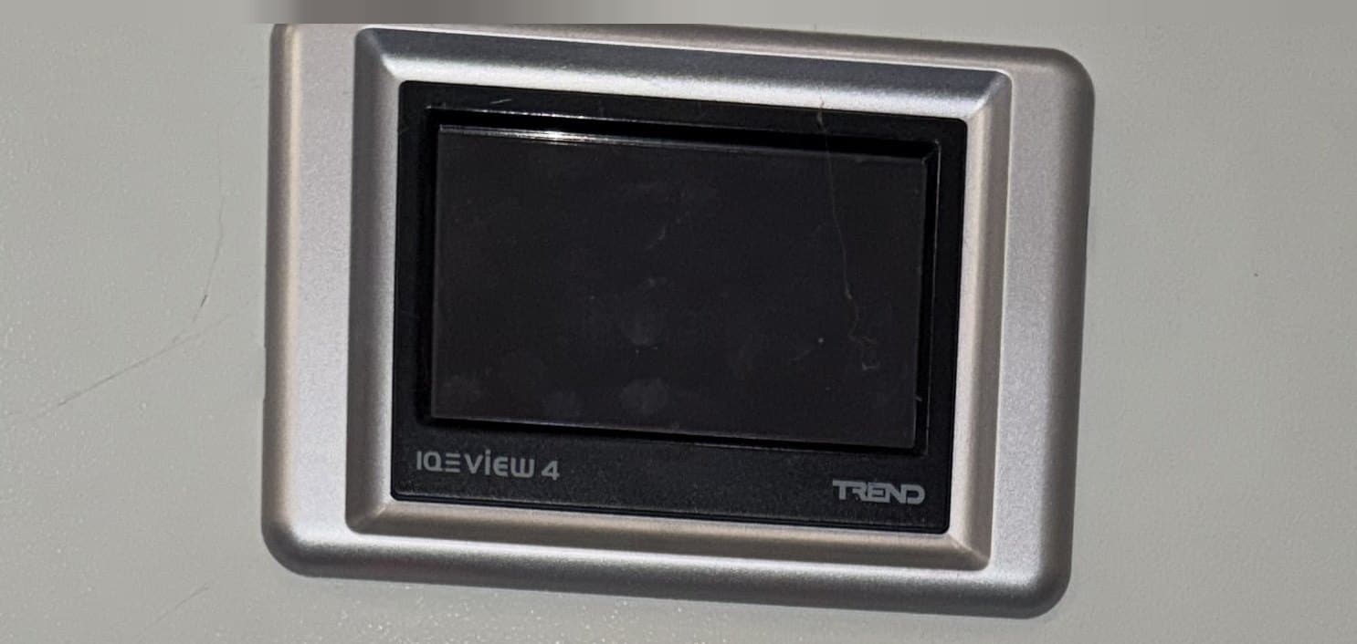
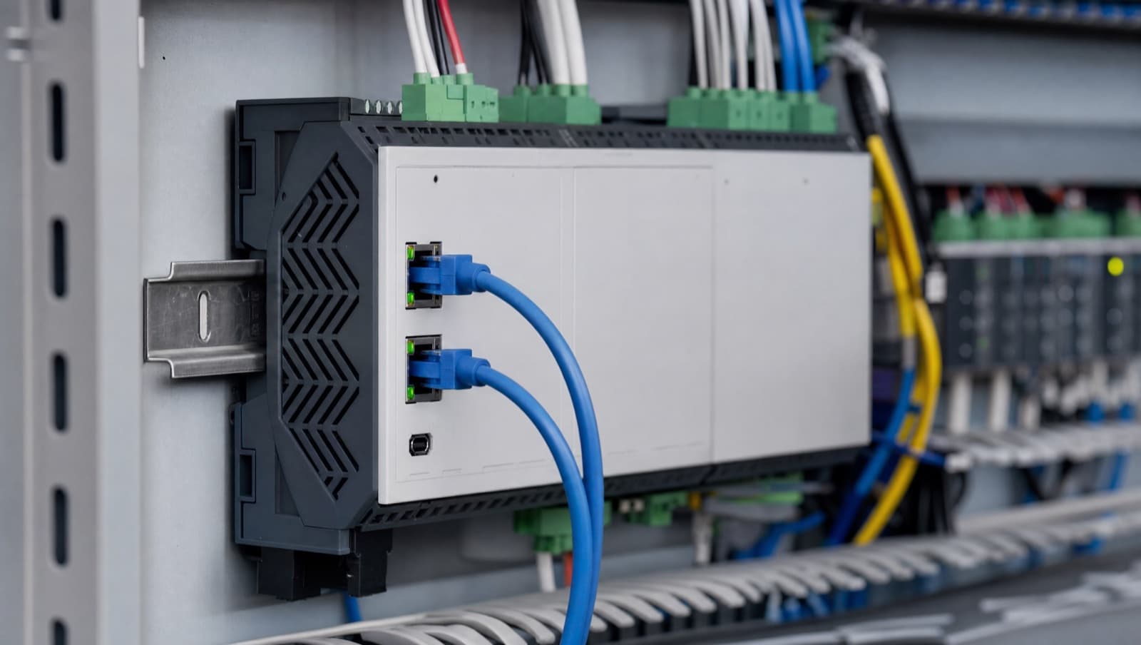
What does get terminated on a current Trend site is the BACnet MS/TP fieldbus — the RS-485 sub-network running out to VAV boxes, FCU controllers and other field devices. Here Trend's own guidance is specific: the trunk must be wired as a straight bus rather than a loop or a star, using tinned copper screened twisted-pair with a characteristic impedance between 100 and 130 ohms. Controllers such as the IQ4NC provide an integral 120Ω terminator that can be switched in or out. The arrangement Trend specifies is that the controller sits at one end of the trunk with its terminator switched in, and a 120Ω resistor is fitted across the MS/TP terminals of the device at the far end.
The practical trap is the switchable terminator itself. Because it is a switch rather than a component somebody has to physically fit, it is easy to leave enabled on a controller that has since been moved into the middle of an extended trunk — and nothing on the panel tells you it is wrong. If you have inherited a Trend site with unexplained MS/TP dropouts, check the terminator switch position on every controller before you replace anything. Trend's product installation instructions are the authority for the specific controller in front of you, and they are worth reading rather than assuming: see Trend Controls for current documentation. If you are working out where a particular controller generation sits in the wider range, our complete guide to Trend BMS systems covers the IQ2 to IQ5 progression and IQVISION. For field wiring and diagnostics specifically, see our guides to BMS wiring, run/fault and HOA on Trend systems and inputs and outputs on the IQ4NC and IQ eco 412.
How do you troubleshoot EOL resistor problems?
Three faults cover most EOL resistor problems on site:
- Intermittent BACnet communication: Usually a missing or incorrect termination resistor. Install a 120Ω resistor at both ends of the MS/TP trunk.
- VAV damper position reads zero: Usually an open circuit in the feedback wiring. Check wiring continuity and install a pull-up resistor if needed.
- Fire panel shows a fault condition: Usually an EOL resistor that's disconnected or the wrong value. Verify the EOL resistor value matches the panel specification.
End-of-line resistors are simple but essential components in BMS, fire alarm, and communication systems. Whether it's BACnet MS/TP termination, VAV controller feedback, or supervised alarm circuits, knowing where and why they're used keeps systems reliable. If you're upgrading a BMS or integrating legacy VAV controllers, proper termination is a small detail that makes a big difference.
Need help with BMS wiring or VAV controller integration? Contact Alpha Controls for expert guidance.
Alpha Controls provides BMS wiring, termination, and signal integrity services across London, Kent, Essex, and the South East. Contact us to discuss your project.
Alpha Controls Team
Specialist BMS installation, commissioning, and maintenance across London and the South East. SafeContractor Approved, BCIA Member.