
A clean, scalable server room comes down to five disciplines: plan the room layout, manage every cable along a defined pathway, label both ends of everything, protect airflow with blanking panels and separation, and document the result. Get those right and you can identify any cable in seconds and patch changes in minutes.
If you've ever opened the door to a server room and been greeted by a wall of tangled cables — colour-coded in theory, spaghetti in practice — you already know why cabling best practices matter. A badly cabled server room doesn't just look unprofessional. It causes real operational problems: blocked airflow leading to thermal shutdowns, accidental disconnections during routine patching, hours wasted tracing cables that should have been labelled, and change windows that run over because nobody can identify which patch lead goes where.
We build and maintain server rooms and comms rooms for commercial buildings across the UK, from single-cabinet setups in small offices to multi-rack suites in data-heavy environments. The principles are the same regardless of scale: plan the layout, manage the cables, label everything, maintain airflow, and document what you've done. It sounds simple. Getting it right takes experience.
How should you lay out a server room before pulling cable?
Before a single cable is pulled, the room layout needs to be right. The position of your cabinets or racks dictates everything — cable runs, airflow paths, power distribution, and future expansion capacity.
For rooms with more than two racks, a hot-aisle/cold-aisle arrangement is essential. Cold air enters from the front of the racks (the cold aisle), passes through the equipment, and exhausts out the back (the hot aisle). ASHRAE TC 9.9 recommends maintaining inlet air temperatures between 18 and 27 degrees Celsius for IT equipment, with the A2 allowable range extending to 10-35 degrees. If your cabling blocks the front of a rack or forces gaps in blanking panels, you're mixing hot and cold air and forcing your cooling system to work harder than it needs to.
Racks should be positioned with at least 1,000mm clearance at the rear for cable management and maintenance access. If you're using floor-standing 42U racks with top-of-rack cable management, you need sufficient ceiling height for vertical cable drops. The distance between rows should accommodate cable trays or ladder rack running overhead without obstructing airflow or lighting.
What does structured cable management actually involve?
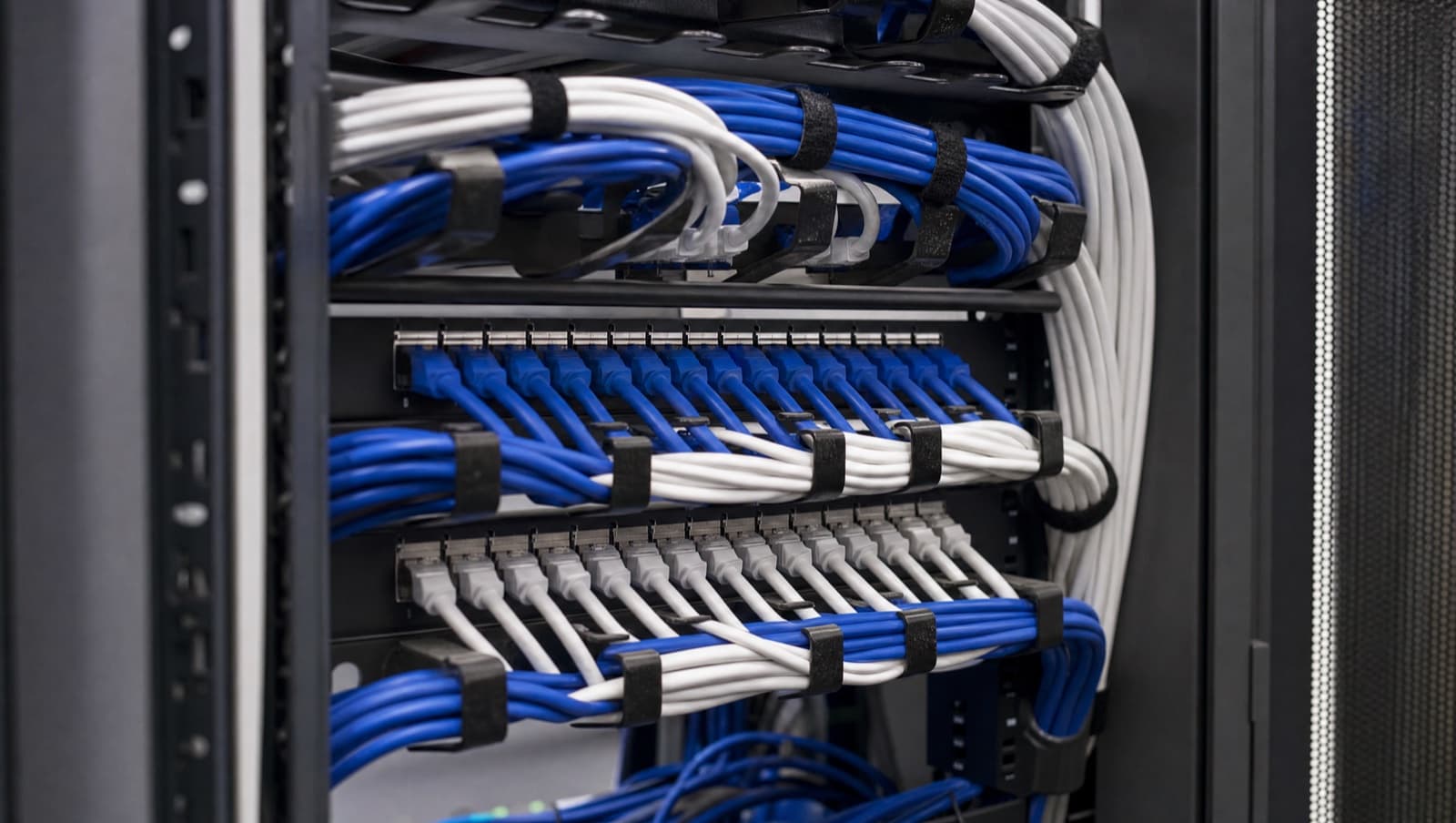
The single biggest difference between a clean server room and a chaotic one is structured cable management. Every cable should have a defined pathway from patch panel to switch, from switch to server, and from server to storage. No cable should be draped, hanging loose, or routed across the floor.
Horizontal cable management panels should be installed between every 1U or 2U of active equipment in a rack. These aren't optional — they're what prevent the gradual accumulation of slack that turns a tidy rack into a mess within six months. Vertical cable managers on both sides of the rack channel cables from horizontal panels to the correct equipment port.
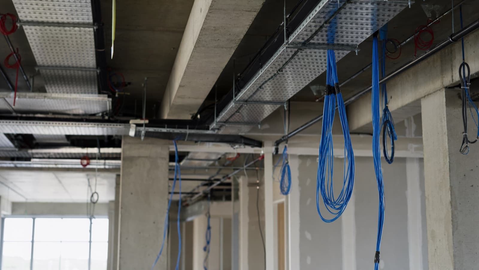
For inter-rack cabling, overhead cable trays or ladder rack are the standard approach. BS EN 50174-2:2018 specifies requirements for cable pathway planning, including fill ratios and separation distances. The 40% fill ratio from TIA/EIA-569 applies here too — if your cable tray is more than 40% full, you need a larger tray or an additional run. Overfilled trays put excessive weight on fixings, create bend radius violations, and make it practically impossible to add or remove individual cables.
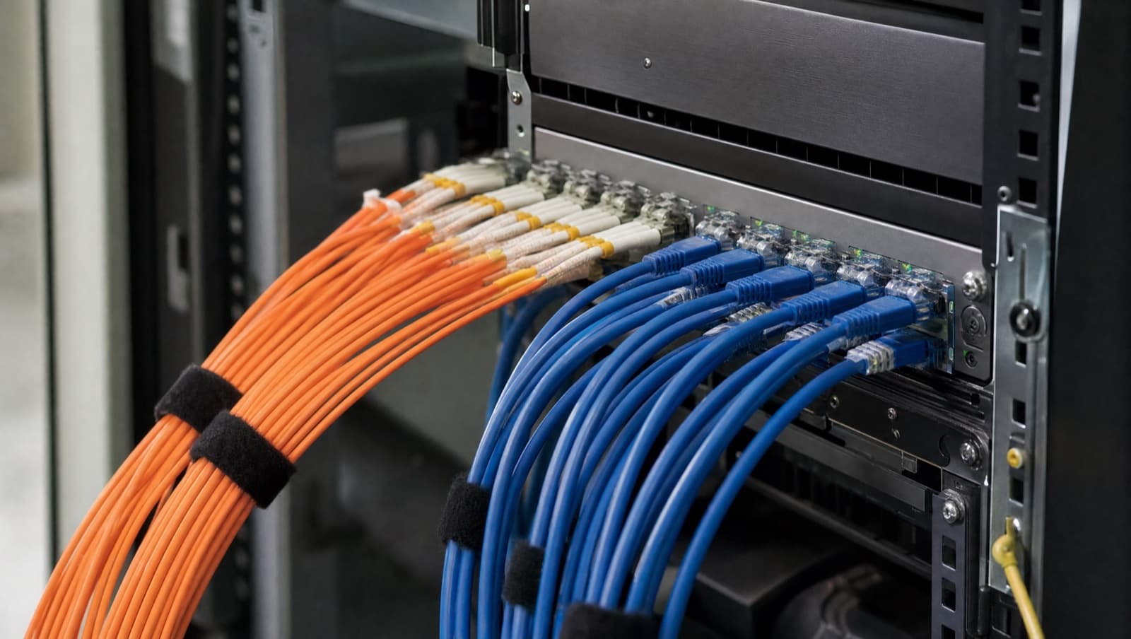
Fibre patch leads deserve special attention. Unlike copper, fibre optic cables have minimum bend radius requirements that are easily violated in a crowded rack. Single-mode fibre (OS2) typically requires a minimum bend radius of 30mm, and some pre-terminated trunk cables specify even larger radii. Dedicated fibre trays or cassettes in the rack protect splices and connectors from mechanical damage.
Why is labelling so important in a server room?
Every cable, every port, every patch panel position, every rack, and every cabinet should be labelled. This is not a nice-to-have — it's a fundamental requirement of any maintainable cabling infrastructure.
BS EN 50174-1:2018 requires that all cabling components are identified using a consistent labelling scheme. The standard calls for labels at both ends of every cable, on every patch panel port, on every outlet, and on all containment routes. The labelling scheme should be documented and available to anyone who needs to work in the room.
A good labelling convention for a server room might look like this: R01-PP01-24 means Rack 01, Patch Panel 01, Port 24. The corresponding cable at the other end carries the same reference. When someone needs to trace a connection at 2 AM during an outage, that label is the difference between a five-minute fix and an hour of cable-tracing with a toner.
Use a proper label printer — Brady BMP21 or Brother PT-E550W are industry standards. Hand-written labels fade, peel, and become illegible. Wrap-around cable labels are better than flag labels for dense environments because they stay put when cables are moved or re-routed.
Get a Free BMS Survey
We'll assess your controls and provide a detailed quotation.
How do patch panels fit into structured cabling?
The patch panel is the heart of structured cabling in any server room. Every horizontal cable from the floor plate terminates at a patch panel, and short patch leads connect the panel to the active switch ports. This separation between permanent cabling and active equipment is fundamental to the structured cabling model defined in BS EN 50173.
For Cat6a installations, use Cat6a-rated patch panels — not Cat6. The connector geometry and contact resistance matter at 500 MHz, and a Cat6 panel can become the weak link in an otherwise Class EA channel. Angled patch panels (24-port in 1U) can reduce cable congestion compared to flat panels, but make sure the angle doesn't compromise the bend radius of the patch leads.
Keep patch leads as short as practical. A 0.5m patch lead where 0.3m would do creates unnecessary clutter; a 3m patch lead where 1m is needed creates a coiled mess behind the panel. Measure your rack layout and stock three or four standard lengths.
How should power and cooling be integrated with cabling?
Cabling doesn't exist in isolation — it shares the rack with power distribution, cooling, and sometimes environmental monitoring. The interaction between these systems is where problems often emerge.
Power cables (PDU feeds, IEC leads) should be routed separately from data cables. BS EN 50174-2 specifies minimum separation distances between power and data cabling to prevent electromagnetic interference. For unscreened data cables running parallel to power cables, a 200mm separation is the baseline. With metallic barriers or screened cabling, this can be reduced.
In-rack PDUs should be mounted vertically at the rear of the rack, with power cables routed down the vertical cable manager. Data cables should run on the opposite side. This physical separation isn't just about EMI — it also means you can work on power without disturbing data connections, and vice versa.
Airflow management ties directly back to cabling discipline. Every unused rack unit should have a blanking panel. Every cable entry point through the rack floor or ceiling should be sealed with brush strips or grommets. EN 50600-2-3 covers environmental control for data centre facilities and emphasises the importance of containment — which starts with not allowing cables to act as air bypass paths.
What documentation should a finished server room have?
A server room without documentation is a liability. Every cable run should be recorded in a structured document or database — source, destination, cable type, length, label reference, and test results.
The as-built documentation should include a rack elevation diagram showing every piece of equipment and its position, a port map showing patch panel to switch connections, a floor plan showing containment routes and cable tray positions, and network topology showing logical connections.
This documentation should be kept in the room (a laminated copy on the inside of the cabinet door is old-school but effective) and in a digital system accessible to the FM team. When we hand over a comms room, we provide Fluke test certificates for every link, a full port map, and rack elevation drawings. If the documentation doesn't exist, the installation isn't complete.
What does a well-built server room look like?
A well-built server room is one where you can walk in, identify any cable within 30 seconds, patch a new connection in under 5 minutes, and trace a fault without pulling everything apart. The racks are clean, the cables follow defined pathways, the labelling is consistent and legible, the airflow paths are unobstructed, and there's a clear record of what connects to what.
It also has room to grow. If every rack position is full, every cable tray is at capacity, and there's no spare patch panel space, the room was under-specified from the start. Good design includes 30% spare capacity for growth — in rack space, cable tray fill, power capacity, and cooling headroom.
When should you remediate an existing server room?
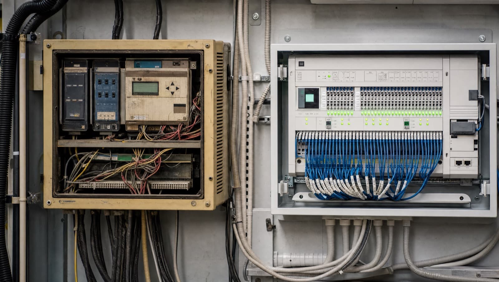
If your server room has become unmanageable — if moves and changes take hours instead of minutes, if you've had outages caused by accidental disconnections, if your cooling system is fighting against cable-blocked airflow — it's time for a structured remediation. We can audit your existing setup, design a clean cable management scheme, re-terminate and re-label everything, and document the result to BS EN 50174 and BS 6701 standards.
If you're building a new comms room from scratch, talk to us at the design stage. Getting the layout, containment, and labelling right from day one costs a fraction of fixing it later — and it means your server room will still be clean and functional in ten years, not ten months. Request a quote and we'll scope it with you.
Alpha Controls Team
Specialist BMS installation, commissioning, and maintenance across London and the South East. SafeContractor Approved, BCIA Member.