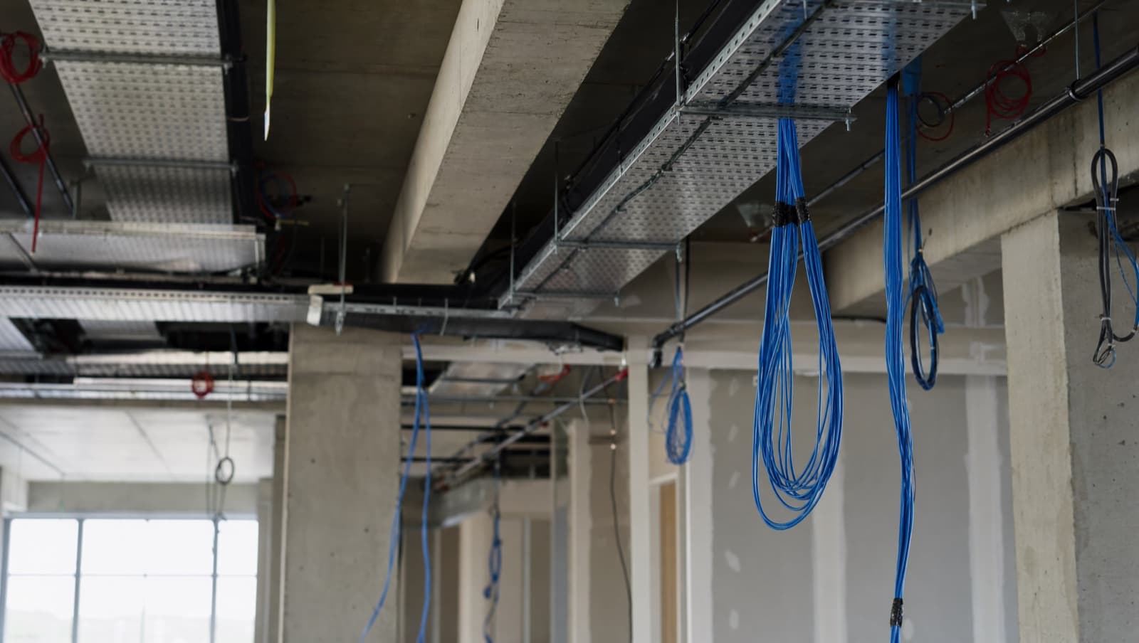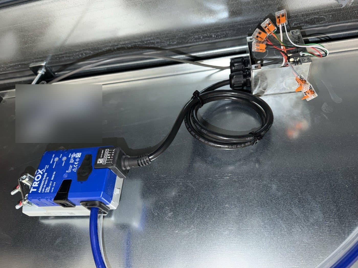

Structured cabling in the UK is governed by BS EN 50173 (what the system must achieve), BS 6701 (how it must be installed), and BS EN 50174 (planning and documentation). Together they define how cable is specified, installed, tested and documented. Ignore them and your install can't be certified or compliant.
There's a persistent myth in commercial building projects that data cabling is somehow less regulated than electrical work. It isn't. Ignore the standards and you end up with an installation that can't be certified, won't perform to spec, and could leave you exposed on insurance and compliance.
The problem is that most building owners, facilities managers and even some M&E contractors don't know what these standards actually require. They see "Cat6a tested and certified" on a handover document and assume everything is fine. But tested to what standard? Certified by whom? Using what equipment? These details matter, and they're spelled out clearly in the relevant British and European standards.
What is BS EN 50173 and what does it cover?
BS EN 50173 is the European standard for generic cabling systems, adopted in the UK as a British Standard. It comes in multiple parts, but the one that matters most for commercial buildings is BS EN 50173-1:2018, which covers the generic cabling structure and requirements for office premises.
This standard defines the cabling hierarchy that every structured cabling system should follow: building distributor, floor distributor, consolidation point (optional), and telecommunications outlet. It specifies performance classes for balanced copper cabling — Class D (Cat5e), Class E (Cat6), Class EA (Cat6a), and higher — along with optical fibre classes for single-mode (OS1, OS2) and multimode (OM1 through OM5) fibre.
Critically, BS EN 50173-1:2018 specifies that each cabling link must meet defined performance parameters including insertion loss, return loss, near-end crosstalk (NEXT), power sum NEXT (PSNEXT), alien crosstalk (for Class EA and above), and propagation delay. These aren't suggestions — they're pass/fail criteria that determine whether your installation is compliant.
The standard also defines maximum channel lengths. For balanced copper cabling, the permanent link (wall outlet to patch panel) is limited to 90 metres, with a total channel length (including patch leads at both ends) of 100 metres. Exceed these distances and your cable won't meet the performance class, regardless of how well it's terminated.
BS EN 50173-2 covers industrial premises, BS EN 50173-3 covers homes, BS EN 50173-4 covers data centres, and BS EN 50173-5 covers campus backbone cabling. If you're working across a multi-building campus or fitting out a data centre, the relevant part applies.
What does BS 6701 require for cabling installation?
While BS EN 50173 defines what the cabling system should achieve, BS 6701:2023 defines how it should be installed. This standard covers the design, installation, and maintenance of telecommunications equipment and infrastructure in customer premises.
BS 6701 is comprehensive. It requires that all installations are carried out by competent persons — meaning trained, qualified cabling installers, not general electricians pulling Cat6 as a side job. It mandates that every installed link is tested using calibrated field testers compliant with the relevant accuracy level (Level V for Class EA testing), and that test results are documented and provided to the client.
The standard also covers practical installation requirements: minimum bend radii for cables (typically 8x the cable diameter for Cat6a during installation, 4x when installed and not under tension), maximum pulling tension (110N for 4-pair cables), and requirements for fire stopping where cables pass through fire-rated walls and floors. If your installer doesn't know the bend radius requirements in BS 6701, they shouldn't be terminating Cat6a.
BS 6701 also addresses earthing and bonding for screened cabling systems. If you're using shielded Cat6a (F/UTP or S/FTP), every screen must be bonded to a common bonding network. An unbonded screen doesn't just fail to protect against interference — it can actually make things worse by coupling noise into the data pairs. This is one of the most common installation faults we see: shielded cable installed without proper bonding, creating more problems than it solves.
What does BS EN 50174 cover for installation planning?
BS EN 50174 sits alongside BS 6701 and covers the planning and installation of cabling infrastructure in more detail. It comes in three parts that matter for commercial installations.
BS EN 50174-1:2018 covers specification and quality assurance. It defines the documentation requirements for a cabling installation — the design specification, the as-built documentation, and the test results that must be provided on handover. If you receive a handover pack that's just a stack of Fluke printouts with no drawing, no port schedule, and no labelling key, the installation doesn't meet BS EN 50174-1.
BS EN 50174-2:2018 covers installation planning and practices inside buildings. This is where you find the separation distance requirements between data cabling and power cables (200mm for unscreened data cable running parallel to power, reduced to 50mm with metallic separation). It also covers containment requirements, environmental conditions during installation (temperature, humidity), and protection against electromagnetic interference.
BS EN 50174-3 covers installation planning outside buildings — campus backbones, external fibre routes, and duct infrastructure.
Get a Free BMS Survey
We'll assess your controls and provide a detailed quotation.
How is structured cabling tested and certified?
Testing is where standards compliance becomes measurable. BS EN 50173 defines the performance parameters; the field tester measures against them. For a Class EA (Cat6a) permanent link, the tester must be equipped with a Level V adapter and calibrated within its 12-month certification period.
The standard testing framework is defined in BS EN 61935-1 (for balanced cabling) and BS EN 61280 (for optical fibre). A permanent link test measures every parameter — insertion loss, NEXT, PSNEXT, ACR-F, return loss, propagation delay, delay skew, and for Class EA, alien crosstalk — and produces a pass or fail result against the specified class.
Every link must pass. Not most links — every link. A result of "PASS*" (marginal pass) on a Fluke tester means the parameter met the standard but was within the measurement uncertainty band. Repeated marginal passes across an installation suggest a systemic termination quality issue that should be investigated.
The test results form part of the as-built documentation and should be stored digitally. Fluke LinkWare software is the industry standard for managing and exporting test results. The results should reference the specific standard and class tested against, the tester serial number, the calibration date, and the adapter type used.
What usually goes wrong with structured cabling installs?
The most common standards failure we encounter isn't a cable that can't pass a test — it's an installation that was never tested at all. We've taken over buildings where the previous cabling contractor provided a "certificate of installation" — a meaningless document with no test data behind it. When we test the links, we find failures. Sometimes 5%, sometimes 30%. Failed links caused by poor termination, excessive untwist, kinked cables, or bend radius violations.
Another common problem is specification mismatch. The design says Cat6a, the cable is Cat6a, but the patch panels are Cat6. Or the faceplates are Cat5e. Or the patch leads are unrated. The cabling channel is only as good as its weakest component, and BS EN 50173 is clear: every component in the channel must meet the specified class.
We also see installations where shielded cable was specified but the earthing and bonding was never completed. The screens are floating, the rack isn't bonded, and the cable is picking up noise from the adjacent power distribution board. The installation technically has Cat6a cable in it, but it isn't a compliant Class EA system because the shielding isn't functional.
What does a standards-compliant cabling install look like?
A standards-compliant structured cabling installation looks like this: every component — cable, patch panel, outlet, patch lead — is rated to the same class. Every link is tested with calibrated equipment and the results are documented. The containment is properly sized with no more than 40% fill ratio. Separation distances from power cabling are maintained per BS EN 50174-2. Screened cabling is properly bonded. Fire stopping is installed and certified. And the as-built documentation includes drawings, port schedules, labelling keys, and digital test results.
If your current installation can't demonstrate all of this, it isn't compliant — regardless of what the original contractor told you.
How should you specify or audit a cabling install?
If you're planning a new structured cabling installation, specify compliance with BS EN 50173-1 Class EA, BS 6701, and BS EN 50174-2 from the start. Write it into the tender specification. Require Fluke certification of every link. Ask for evidence of installer competence.
If you have an existing installation and you're not sure whether it meets current standards, we can carry out a cabling audit — testing every link, checking the containment and labelling, verifying the documentation, and providing a clear report on what's compliant and what needs remediation. Get in touch and we'll give you a straight answer.
Alpha Controls Team
Specialist BMS installation, commissioning, and maintenance across London and the South East. SafeContractor Approved, BCIA Member.