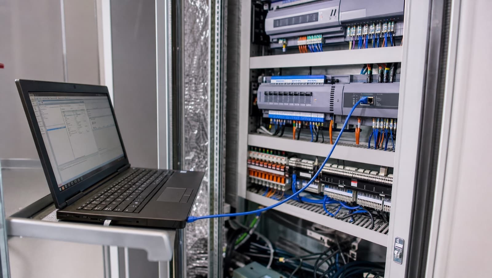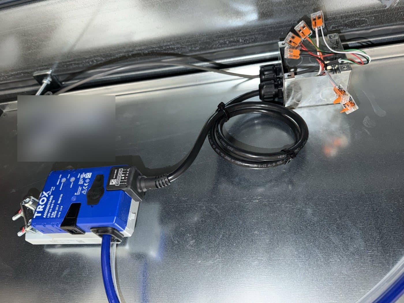

Most Modbus metering faults are physical, not software. RS-485 wiring problems — star topology instead of daisy-chain, missing 120 ohm termination, reversed A/B polarity, or register-map errors such as byte-order mismatches and missing scaling factors — cause the majority of zero readings, garbage values, and intermittent dropouts Alpha Controls diagnoses across London and Kent.
The meter data is not coming through. Your energy reports show gaps, the M&E contractor wired the Modbus trunk six months ago, and the readings are garbage — negative power values, kWh counters that jump by thousands overnight, or meters that simply show zero. You have had three different engineers look at it. One said it was a software issue, another blamed the meters, and the third suggested replacing the entire bus. Meanwhile, you cannot produce accurate energy reports, tenant billing is estimated rather than measured, and your DEC rating is based on incomplete data.
This is one of the most common problems Alpha Controls is called to resolve across London and Kent. Modbus integration — particularly RS-485 wiring for energy meters — accounts for a significant proportion of our reactive callout work. The protocol itself is simple and reliable. The problems are almost always in the physical wiring, the register mapping, or the configuration. This guide covers the real-world Modbus faults we diagnose every week and how we fix them.
What is Modbus and how is it used in building management?
Modbus is a serial communication protocol developed by Modicon (now Schneider Electric) in 1979 for industrial control systems. It has become one of the most widely deployed protocols in building management because it is simple, reliable, well-understood, and royalty-free. The Modbus Organisation maintains the protocol specification, which is freely available at modbus.org.
In BMS environments, Modbus exists in two primary variants:
- Modbus RTU — communicates over RS-485 serial cabling using binary encoding. This is the standard for field devices: energy meters, heat meters, gas meters, water meters, variable speed drives, fan coil unit controllers, and packaged plant. RTU stands for Remote Terminal Unit.
- Modbus TCP — communicates over standard Ethernet using TCP/IP, wrapping the same Modbus function codes in TCP packets. Used for IP-native devices, long-distance communication, and integration with IT networks.
Modbus uses a master/slave architecture (also called client/server in newer documentation). The BMS controller or gateway acts as the master, polling each slave device in turn — requesting register values (reads) or sending commands (writes). Slaves cannot initiate communication; they only respond when polled. This is fundamentally different from BACnet, which allows peer-to-peer communication and event-driven notifications.
The master/slave model means that Modbus network performance is directly related to the number of devices and registers being polled. More devices and more data points mean longer poll cycles and higher latency. Alpha Controls designs Modbus networks with appropriate poll intervals and register selections to balance data freshness against bus loading.
Why does RS-485 wiring cause most Modbus failures?
If we had to identify the single biggest cause of Modbus failures in commercial buildings, it would be RS-485 wiring. The protocol is robust. The devices are reliable. But the physical layer — the cable, the connections, the topology — is where almost everything goes wrong. The faults below account for the overwhelming majority of RS-485 problems on site.
Topology: Daisy-Chain, Not Star
RS-485 requires a strict daisy-chain (bus) topology. The cable must go from Device 1 to Device 2 to Device 3 and so on, with the master at one end (or at any point on the chain). What we frequently find on site is star wiring — a central junction box with individual cable runs radiating out to each meter. This creates unterminated stubs that cause signal reflections, impedance mismatches, and intermittent communication failures that are maddening to diagnose because they come and go unpredictably.
If the physical layout of the building makes a pure daisy-chain impractical, Alpha Controls installs RS-485 hubs or repeaters that create properly terminated segments for each branch.
Termination: Two Resistors, Both Ends, Nowhere Else
Each RS-485 bus must have a 120 ohm termination resistor at each physical end of the cable. These resistors absorb the signal energy at the end of the line, preventing reflections that would corrupt data. Missing termination is one of the top three Modbus faults we encounter. Equally problematic is over-termination — adding resistors at intermediate points or at every device, which changes the characteristic impedance and causes different but equally frustrating communication errors.
Polarity: A and B Are Not Universal
RS-485 uses differential signalling on two wires. One manufacturer labels them A(-) and B(+). Another labels them D+ and D-. A third uses T/R+ and T/R-. There is no universal standard for terminal labelling. If polarity is reversed at any single device, that device corrupts the entire bus. Alpha Controls verifies polarity with an oscilloscope during commissioning rather than relying on terminal labels, which are demonstrably inconsistent across manufacturers.
Cable Specification and Routing
RS-485 requires shielded twisted-pair cable — typically Belden 9841 or equivalent with 120 ohm characteristic impedance. We frequently find installations using Cat5e, unshielded telephone cable, or even mains-rated cable for RS-485 runs. These can work over short distances in quiet environments but fail in buildings with variable speed drives, power distribution boards, and lift motors generating electromagnetic interference.
Cable routing is equally critical. RS-485 cables must be separated from power cables by a minimum of 300mm, and from lighting circuits by 150mm. Running Modbus cable inside a power tray — which we see regularly — is a recipe for intermittent communication failures caused by induced EMI.
Bias Resistors: The Forgotten Component
When no device is transmitting on an RS-485 bus, the line floats to an undefined voltage state. This can cause receivers to interpret noise as valid data, generating false characters and CRC errors. Bias resistors (typically 390-560 ohm) pull the bus to a defined idle state. Many RS-485 transceivers have built-in bias, but in long cable runs with many devices, external bias resistors at the master end are essential. Alpha Controls checks for and installs bias resistors as part of every Modbus commissioning.
How does Modbus energy metering integration work in a BMS?
The most frequent reason Alpha Controls is asked to install or troubleshoot Modbus in commercial buildings is energy metering integration. Virtually every commercial energy meter — Schneider iEM series, ABB EQ meters, Socomec Diris, Eastron SDM, Carlo Gavazzi EM series — ships with Modbus RTU as the standard communication interface. Reading those meters reliably depends on correct register mapping, scaling, and byte order.
Register Mapping: The Critical Step
Unlike BACnet, which is self-describing (you can browse a BACnet device and discover its data points), Modbus is opaque. The data lives in numbered registers, and without the manufacturer's register map, you have no way of knowing what register 1234 contains. Each meter manufacturer provides a register map document listing:
- Register addresses for each parameter (voltage, current, power, energy, power factor)
- Data types (16-bit integer, 32-bit integer, 32-bit float, 64-bit float)
- Byte order (big-endian or little-endian, and word order for 32-bit values)
- Scaling factors (some meters store kWh as an integer with an implied decimal point)
- Read/write access (most meter registers are read-only; configuration registers may be read-write)
Getting the register mapping wrong produces the classic symptoms: values that are clearly impossible (negative power, voltage readings of 0.003, energy counters that overflow), values that are in the wrong units (kW displayed as MW because a scaling factor is missing), or values that read as zero because the wrong data type is being parsed. Alpha Controls maintains a library of register maps for all common metering equipment and verifies every mapping on site during commissioning.
Scaling Factors and Byte Order
Two of the most common causes of "the meter is reading but the values are wrong" are byte-order mismatches and missing scaling factors. A 32-bit floating-point value occupies two consecutive 16-bit Modbus registers. Some devices transmit the high word first (big-endian), others transmit the low word first (little-endian). If the BMS controller reads the words in the wrong order, the resulting floating-point value is nonsense — often a very large or very small number that looks plausible enough to go unnoticed for months.
Scaling factors are equally treacherous. Some meters store energy as a raw integer count of watt-hours, which needs dividing by 1000 to display kWh. Others store kWh directly as a float. Getting this wrong means your energy reports are off by a factor of 1000 — either showing your building consumes nothing or consumes as much as a small city.
Pulse Counting vs Register Reading
Older metering installations use pulse outputs rather than Modbus — the meter generates a pulse for every kWh (or fraction of kWh) consumed, and the BMS controller counts pulses. This approach is less accurate than reading cumulative energy registers via Modbus (pulses can be lost during controller resets or power failures) and provides less data (only kWh, no real-time power, voltage, or current). Alpha Controls recommends Modbus register reading for all new metering installations and can retrofit Modbus communication to existing meters that support it.
Get a Free BMS Survey
We'll assess your controls and provide a detailed quotation.
When should you use Modbus instead of BACnet?
Modbus and BACnet are complementary protocols, and most commercial buildings in London and Kent use both. The choice of which to use for each device or system depends on the device capability and the integration requirements.
Use Modbus when:
- The device only supports Modbus (most energy meters, many VFDs, packaged plant)
- The integration is straightforward read-only data (meter readings, status monitoring)
- Cost is a primary concern (Modbus devices and cabling are generally cheaper)
- The device count per bus is low (under 30 devices)
Use BACnet when:
- The device is a BMS controller managing HVAC systems
- You need event-driven notifications (COV) rather than polling
- You need scheduling, alarming, or trend logging at the device level
- Multi-vendor interoperability is critical
- The installation must comply with BS EN ISO 16484-5
In practice, a typical BMS installation uses BACnet IP/MS/TP for the main controller network and Modbus RTU for metering, drives, and third-party equipment. Protocol gateways or controllers with built-in Modbus master ports bridge the two networks. For more detail on BACnet, see our BACnet installation and troubleshooting guide.
How does Alpha Controls troubleshoot Modbus faults?
When Alpha Controls is called to diagnose Modbus communication faults, we follow a systematic process that starts at the physical layer and works upward. Guessing is not an option — Modbus faults are too varied and too subtle for trial-and-error approaches.
Step 1: RS-485 Physical Layer Testing
We start with cable testing: continuity, insulation resistance, and shield integrity. We verify the topology is true daisy-chain with no star connections or unterminated stubs. We measure termination resistance (should be approximately 60 ohms end-to-end with both terminators in place). We check for bias resistors at the master end.
Step 2: Signal Quality Analysis
Using an oscilloscope connected to the RS-485 lines, we examine the signal waveform. A healthy RS-485 signal has clean differential transitions with amplitude of at least 200mV and no ringing, overshoot, or noise corruption. We can identify termination problems (ringing after transitions), EMI interference (high-frequency noise superimposed on the signal), and ground loops (low-frequency distortion) directly from the waveform.
Step 3: Protocol Analysis
We connect a Modbus protocol analyser (software tool on a laptop with an RS-485 adapter) to the bus and capture live traffic. This shows us every request and response, including CRC errors, timeout failures, and devices that respond slowly or inconsistently. We can identify specific devices causing problems, verify that addressing is correct, and confirm that baud rate and parity settings match between master and all slaves.
Step 4: Device-Level Verification
For metering integrations, we verify each meter's register mapping by reading raw register values with the protocol analyser and comparing them to the meter's local display. This catches byte-order mismatches, scaling errors, and incorrect register addresses that produce wrong but superficially plausible values.
Which standards govern Modbus installation in UK buildings?
Modbus installation in UK commercial buildings should reference the following standards, which cover everything from the BMS integration context to the underlying RS-485 electrical layer:
- BS EN ISO 16484-5 — building automation data communication protocols, which covers the broader BMS context within which Modbus devices operate
- CIBSE Guide H — Building Control Systems, referencing integration of metering and third-party devices into BMS platforms
- EIA/TIA-485-A — the electrical standard for RS-485 balanced multipoint communication
- Modbus Application Protocol Specification — published by the Modbus Organisation at modbus.org
Alpha Controls installs and commissions Modbus networks in compliance with these standards and provides documentation for building handover packages.
What does a real Modbus metering fix look like on site?
A property management company in Kent needed accurate sub-metering for a 6-floor multi-tenanted office building. The M&E contractor had installed 24 Schneider iEM3255 energy meters during the refurbishment, wired on two RS-485 buses (12 meters per floor group), connected to Modbus-to-BACnet gateways feeding the Trend IQVISION supervisor. The system had been "commissioned" six months earlier but the facilities team reported that eight of the 24 meters showed zero readings, three showed obviously incorrect values, and the remaining thirteen would intermittently drop offline for hours at a time.
Alpha Controls was called to diagnose. Our findings: one bus had star wiring from a junction box on the 3rd floor rather than daisy-chain, causing signal reflections; termination resistors were missing from both buses; three meters had their A/B terminals reversed; the Modbus-to-BACnet gateway was configured for big-endian byte order while the iEM3255 meters use little-endian for 32-bit float registers; and two meters had duplicate Modbus addresses. We rewired the star section as a proper daisy-chain, installed termination resistors, corrected the polarity, updated the gateway byte-order configuration, and resolved the addressing conflict. All 24 meters were reading correctly within a single site visit.
Frequently Asked Questions
How much does Modbus metering integration cost for a commercial building?
Costs depend on the number of meters, cable run distances, and whether a new RS-485 bus needs installing or an existing one needs troubleshooting. Installing and commissioning a new Modbus metering bus with 10-20 meters, gateway, and BMS integration typically costs £5,000-£15,000. Troubleshooting an existing faulty Modbus installation typically costs £800-£2,500 depending on complexity. Alpha Controls provides fixed-price quotations after site survey.
Can you integrate Modbus meters into our existing BMS?
Yes. Most modern BMS platforms — Trend IQVISION, Distech EC-Net, Honeywell Niagara, Siemens Desigo — support Modbus integration either through built-in Modbus master ports on controllers or through Modbus-to-BACnet gateways. Alpha Controls handles the complete integration: RS-485 wiring, gateway or controller configuration, register mapping, BMS point creation, and graphic display setup.
Our Modbus devices work individually but fail when all connected — why?
This is a classic RS-485 bus loading problem. Each device works fine in isolation because there are no signal reflections or interference from other devices. When all devices are connected, the cumulative effect of improper termination, star wiring stubs, or excessive cable length causes signal degradation. Alpha Controls diagnoses this with oscilloscope measurements showing signal quality degradation as devices are added to the bus.
Can Modbus RTU and Modbus TCP devices coexist on the same BMS?
Yes, but they require different physical connections. RTU devices connect via RS-485 serial, TCP devices connect via Ethernet. Both can feed data to the same BMS supervisor through appropriate interfaces. Many BMS controllers support both RTU and TCP simultaneously. Alpha Controls designs hybrid Modbus networks where both variants are in use.
How often should Modbus metering data be polled?
For energy monitoring and reporting, 15-minute poll intervals are typically sufficient and align with half-hourly metering requirements. For real-time power monitoring or demand management, 1-5 second poll intervals may be needed. The poll interval must balance data freshness against bus loading — polling too frequently on a large RS-485 bus causes timeouts as the master cannot complete its poll cycle before starting the next one. Alpha Controls optimises poll intervals for each installation.
What is the lifespan of a Modbus RS-485 installation?
A properly installed RS-485 Modbus bus — correct cable specification, proper termination, daisy-chain topology, adequate separation from power cables — will operate reliably for 15-20 years. The cable does not degrade significantly, and the protocol has not changed. Failures typically result from physical damage (building works cutting cables), environmental changes (new VFDs installed near cable routes creating EMI), or modifications that break the topology (adding devices without maintaining daisy-chain).
Get In Touch
If you need a Modbus installer in Kent, London, or the South East — whether for new energy metering integration, RS-485 wiring installation, troubleshooting communication faults, or Modbus-to-BACnet gateway configuration — contact Alpha Controls. Call us on 01474 552200, email info@alphacontrols.io, request a quote or get in touch, or visit alphacontrols.io. For commercial controls work in the capital, see BMS installation across London.
Related guides: BACnet Installers in London and Kent | BMS Maintenance Contracts Guide | BMS Installers in Kent
External references: CIBSE Guide H | Modbus Organisation Protocol Specifications
Alpha Controls
Specialist BMS installation, commissioning, and maintenance across London and the South East. SafeContractor Approved, BCIA Member.