
Data centre water leak detection uses addressable distance-measuring cable run along chilled water pipes, condensate drains and CRAC/CRAH unit bases, reporting leak position to within one metre. It must integrate into the BMS via Modbus TCP and the DCIM via SNMP so alarms trigger zone-based valve isolation, CRAC sequencing and SMS escalation within seconds.
A single litre of water in the wrong place inside a data centre can cause more financial damage in thirty seconds than most commercial buildings suffer in a year. Server racks, power distribution units, network switches, and storage arrays are not designed to tolerate moisture — and unlike an office where a burst pipe means wet carpet and a few ruined ceiling tiles, a water ingress event in a data centre means hardware destruction, data loss risk, and downtime that can run into millions of pounds per hour for the tenants relying on that facility.
The irony is that data centres are full of water. Chilled water pipe runs feed precision cooling units. Condensate drains carry moisture away from CRAC and CRAH units. Humidification systems inject water vapour to maintain the tight humidity envelope that IT equipment demands. Some facilities use direct evaporative cooling or rear-door heat exchangers with chilled water circulation. Every one of these systems introduces water into an environment where water is the single most destructive element after fire — and in many data centres, the leak detection provision is either absent, poorly designed, or installed but not integrated into anything that would actually trigger a meaningful response.
This post covers the design, standards, manufacturer options, and BMS integration approach for leak detection in data centres — from the sensing cable layout under raised floors to the alarm escalation logic that gets the right people moving within seconds.
What does data centre leak detection involve?
Leak detection in a data centre is fundamentally different from leak detection in a standard commercial building. The sensing technology, the alarm priority, the response time requirement, and the integration architecture are all more demanding — because the consequence of a missed detection is not property damage and an insurance claim, it is a facility-level incident that can breach SLA commitments and destroy client relationships.
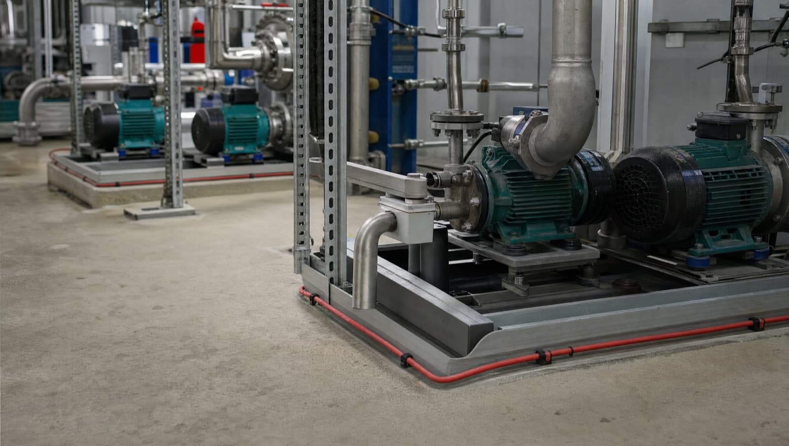
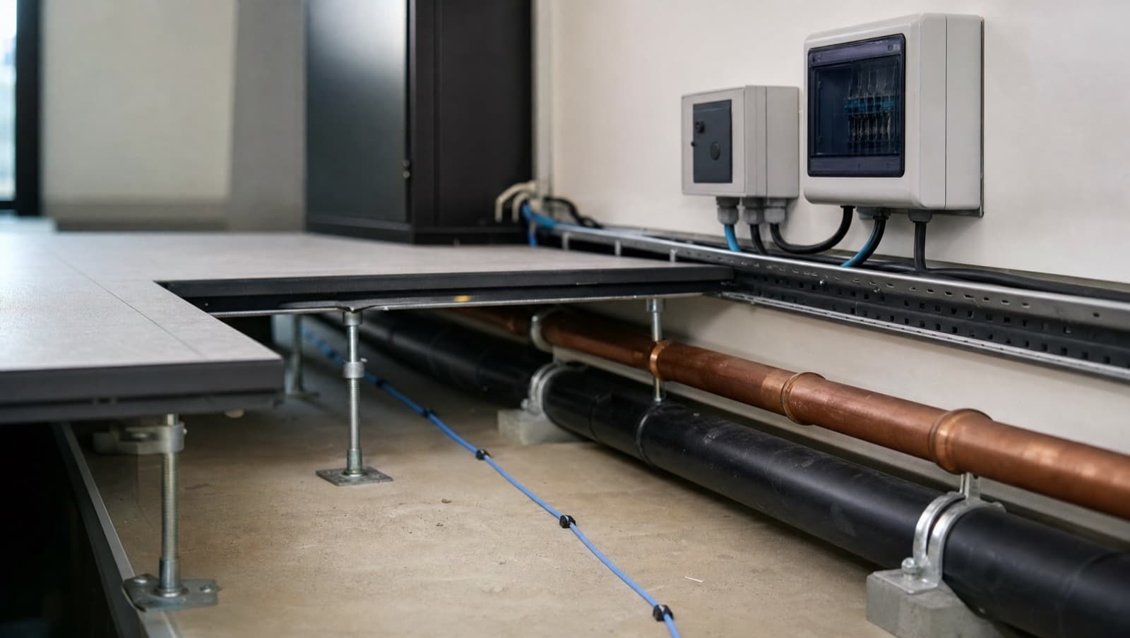
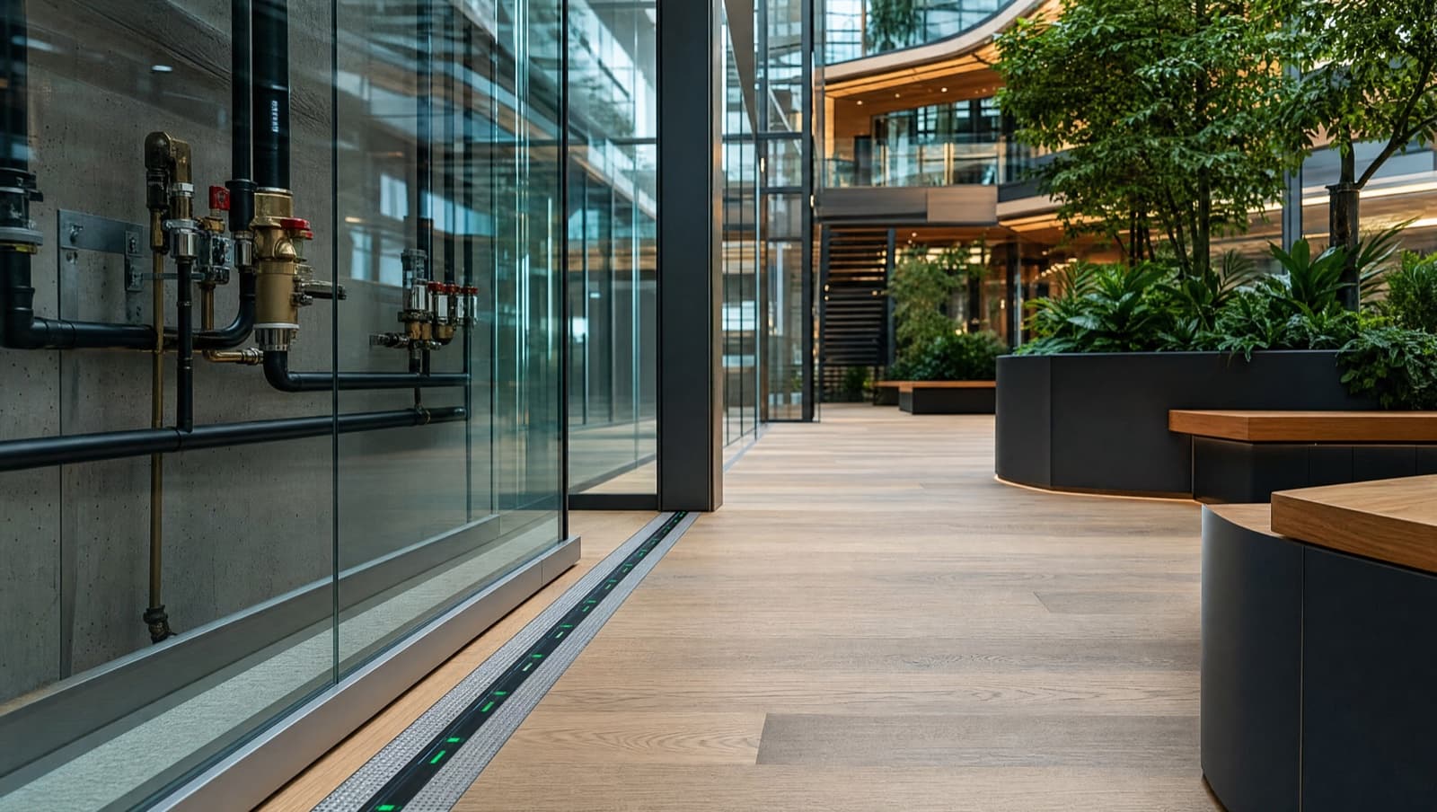
The primary sensing technology for data centres is addressable distance-measuring cable. Unlike point sensors that detect water at a single location, addressable cable runs along the full length of a pipe route, under raised floors, around CRAC and CRAH unit bases, and through riser shafts — and when water is detected anywhere along the cable, the system reports the exact location to within one metre. This matters in a data centre because the difference between a leak at row 14 and a leak at row 38 determines which cabinets are at risk and which isolation valves need to close.
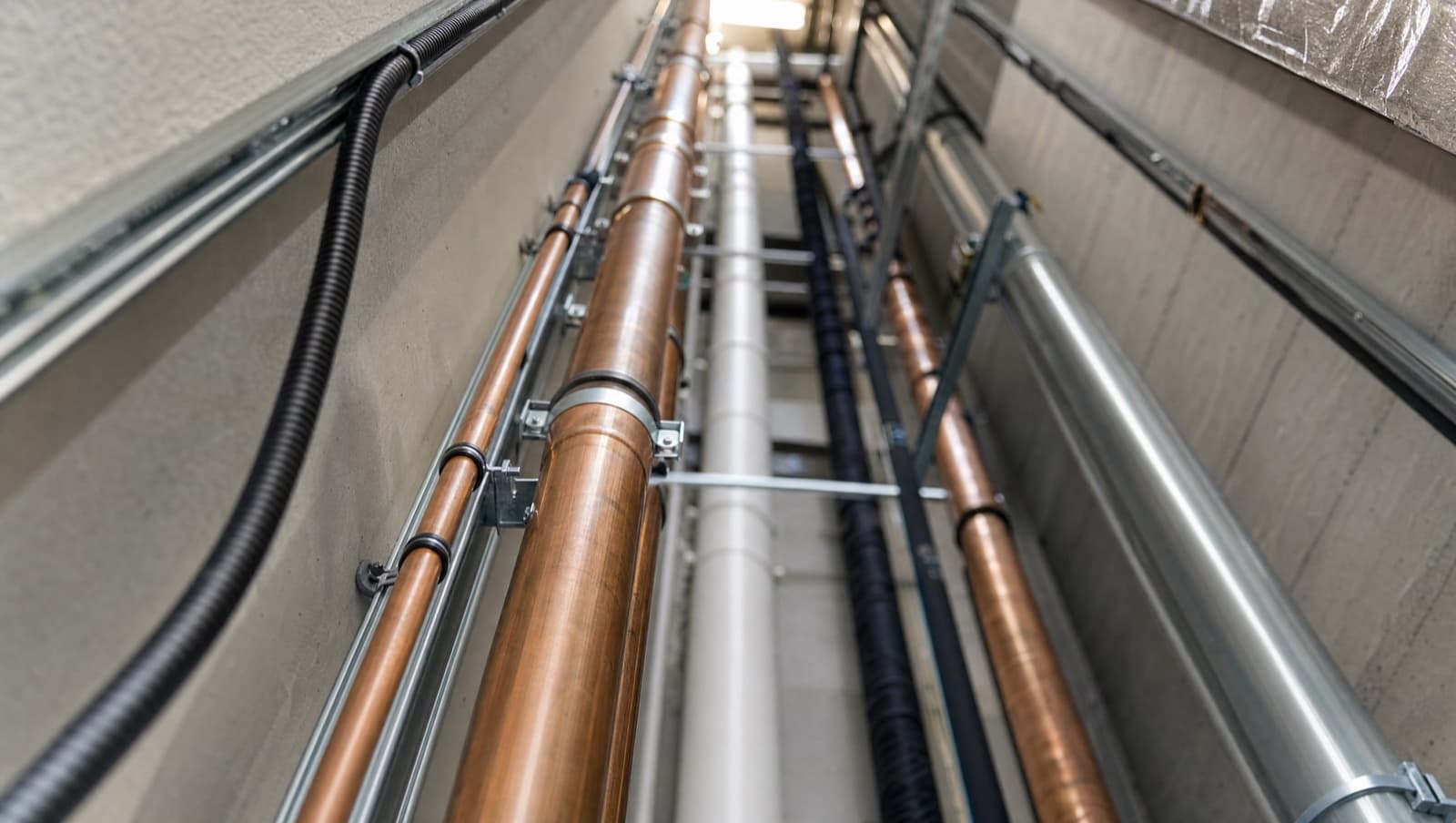
The cable is laid in a specific pattern dictated by the water risk map of the facility. Under raised floors, it follows the chilled water pipe routes from the plant room or rooftop AHU penetration through to the CRAC/CRAH units. Around each precision cooling unit, the cable loops to cover the condensate drain tray and any chilled water valve assemblies. In riser shafts, it runs vertically alongside the chilled water risers to catch any joint or flange failure. Where overhead chilled water distribution is used instead of under-floor routing, the cable is installed in drip trays beneath the pipe runs — because gravity means a leak above the IT load is worse than a leak below it.
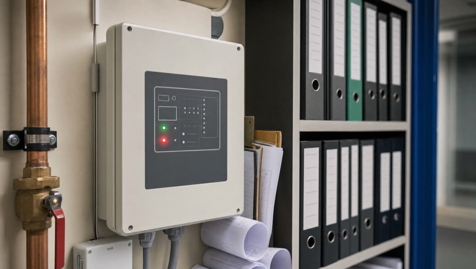
Above the sensing layer sits the detection panel — a dedicated controller that manages the cable inputs, calculates leak position from resistance or capacitance measurements, and generates alarm outputs. In a properly specified data centre, this panel has dual power supply (mains plus UPS-backed), battery backup for panel-level resilience, and redundant communications paths to the BMS and DCIM (Data Centre Infrastructure Management) platform. A single point of failure in the detection chain — one power supply, one communication link, one panel — is not acceptable in any facility operating above Tier I.
Why are data centres the highest-risk environment for water damage?
The risk profile of a data centre is uniquely severe because it combines two factors that do not coexist anywhere else: a high density of water-bearing services and a high density of equipment that is catastrophically sensitive to water.
A typical commercial office might have four or five chilled water pipe runs in the ceiling void serving FCUs. A data centre of equivalent floor area might have forty or fifty, serving precision cooling units that reject tens or hundreds of kilowatts per unit. The total volume of chilled water circulating within the data hall and its supporting plant rooms can be thousands of litres — all of it under pressure, all of it flowing continuously, all of it within metres of live IT equipment.
Condensate is the hidden risk that many data centre operators underestimate. Every CRAC and CRAH unit produces condensate as it cools the return air below its dew point. That condensate is collected in drip trays and drained — typically via small-bore plastic pipework to a common drain. When a condensate drain blocks — and they do, frequently, from biological growth and particulate contamination — the drip tray overflows, and water runs across the raised floor directly towards the nearest cabinet row. We have attended data centres where condensate overflow has been running for hours, tracked under the raised floor by gravity to the lowest point, and pooled around the base of a cabinet run that was fortunately powered down for maintenance. If that row had been live, the damage would have been measured in the hundreds of thousands.
The cooling dependency creates a second-order risk that makes leak detection design more complex. In an office building, an automatic shut-off valve on the incoming water supply is a straightforward decision — you close the valve, the building loses water, someone goes to fix the leak, and the disruption is minor. In a data centre, closing the chilled water supply means the precision cooling units lose their cooling medium. Within minutes, the IT load starts to overheat. Within tens of minutes, equipment begins thermal shutdown. The leak detection system has to be designed so that it can isolate a specific zone or pipe run — not the entire chilled water circuit — to contain the leak while maintaining cooling to the rest of the facility. This is where the integration between leak detection and the BMS becomes critical, and it is the angle that no competitor in this space is covering properly.
What usually goes wrong with data centre leak detection?
The most common failure Alpha Controls encounters in data centre leak detection is the installation that was specified for compliance but designed without any understanding of how a data centre actually operates.
The first pattern is under-floor cable that follows the wrong route. The cable is installed in a grid pattern covering the general floor area, but it does not specifically follow the chilled water pipe runs. A leak from a chilled water joint under the raised floor will track along the pipe route by gravity before it spreads laterally — and if the sensing cable is two metres away running in a different direction, the leak can spread for minutes before it reaches the detection zone. The cable must follow the pipes. That sounds obvious, but we see the alternative on at least a third of the data centre surveys we carry out.
The second pattern is condensate monitoring that does not exist. The CRAC and CRAH units have drip trays, the drip trays have drains, and nobody has put a sensor at the overflow point of the drip tray or along the condensate drain route. The assumption is that the condensate system is a self-managing closed loop. It is not. Drains block, trays corrode, floats fail, and the first indication of a condensate problem is water on the raised floor tiles.
The third pattern is alarm integration that stops at the panel. The detection system has a panel in the plant room or a comms room, and that panel has a screen showing the cable map and alarm status. But it is not connected to the BMS, it is not connected to the DCIM platform, it does not send SMS or email alerts, and there is no alarm escalation protocol defined. At 3am on a Sunday, an alarm on a panel that nobody is watching is not an alarm — it is a log entry that will be discovered during the next working day, by which time the damage is done. Integration into the BMS via Modbus TCP or into the DCIM via SNMP is not optional in a data centre — it is the entire point of having detection in the first place.
The fourth pattern is the absence of any maintenance or testing regime. Sensing cable that has been under a raised floor for five years accumulates dust, gets kinked by cable management changes, gets damaged when floor tiles are lifted for maintenance access. If the cable is not tested annually — by applying water at known positions and confirming that the panel reports the correct location — its reliability degrades silently. Our post on leak detection maintenance and testing covers the testing methodology in detail, and every point in it applies with additional urgency to data centre environments.
Get a Free BMS Survey
We'll assess your controls and provide a detailed quotation.
What standards require leak detection in data centres?
Two standards carry specific authority for data centre leak detection, and both are referenced in colocation contracts and Tier certification requirements.
EN 50600-2-3:2019 — Data Centre Facilities and Infrastructures: Part 2-3: Environmental Control. This is the European standard that defines environmental monitoring and control requirements for data centres. Section 6.3 explicitly addresses water leak detection, requiring that leak detection systems be installed along all water-bearing pipe routes within the data centre hall and supporting plant rooms. The standard specifies that detection systems must provide location information — not just a binary wet/dry alarm — and that alarm outputs must be integrated into the facility monitoring system with defined response protocols. For facilities designed to EN 50600 Availability Class 3 or 4 (broadly equivalent to Uptime Institute Tier III and IV), the standard requires redundancy in the detection infrastructure: dual communication paths from detection panels to the monitoring system, battery backup on panels, and no single point of failure in the alarm chain. EN 50600 is published by CENELEC and is increasingly referenced in UK data centre specifications as the baseline environmental monitoring standard.
Uptime Institute Tier Standard — Topology. The Uptime Institute's Tier classification system does not prescribe specific leak detection products, but it does require environmental monitoring as part of the facility infrastructure. For Tier III (Concurrently Maintainable) and Tier IV (Fault Tolerant) facilities, the monitoring infrastructure — including leak detection — must be maintainable without shutting down the IT load, and must not contain single points of failure that could result in an undetected environmental event. In practice, this means that detection panels must have redundant power, communication paths must be diverse, and the cable layout must be designed so that a single cable failure does not create a blind spot in the detection coverage. The Uptime Institute publishes the Tier Standard documentation, and any facility pursuing Tier certification will need to demonstrate compliance during the certification audit.
Beyond these two, ASHRAE TC 9.9 A2 defines the IT equipment thermal envelope — inlet temperatures of 10-35 degrees Celsius and relative humidity of 20-80% — which provides the context for why cooling systems must remain operational and why leak detection design must balance water damage prevention against cooling continuity. And ISO/IEC 27001, the information security management standard, includes physical environment controls within its Annex A requirements, which are increasingly interpreted to include water ingress protection as part of the physical security perimeter for IT assets.
Which manufacturers supply data centre leak detection systems?
Three manufacturers dominate the UK data centre leak detection market, each with distinct capabilities that suit different facility types and integration requirements.
TTK manufactures addressable sensing cable systems with the FG-NET platform as their data centre flagship. The FG-NET system supports up to 500 individual cable lengths per controller, with leak location accuracy of one metre along each cable. Communication is via Modbus TCP for BMS integration and SNMP for direct DCIM platform connectivity — both of which are critical for data centres where the BMS and DCIM are separate systems managed by separate teams. TTK cable is FM Approved, which satisfies FM Global insurance requirements, and the system supports automatic cable testing to verify integrity without manual water application. The FG-NET controller includes a web server interface for local management, dual Ethernet ports for redundant network connectivity, and configurable alarm thresholds to distinguish between a drip and a flow.
Andel produces the Floodline HLD (High-performance Leak Detection) system, which supports cable runs of up to 1,500 metres per zone with leak location accuracy of plus or minus one metre. The HLD panel supports up to 352 individually addressable zones, making it suitable for large-scale facilities with extensive pipe networks. Communication is via Modbus RTU or Modbus TCP, with volt-free relay outputs available for direct BMS integration. Andel's cable is designed for under-floor installation in data centre environments and is resistant to the dust and particulate contamination that accumulates in raised-floor voids. The Andel website has the full HLD specification, and their technical team provides layout design support for complex installations.
TraceTek (by nVent) and Aquilar provide sensing cable systems that communicate natively via Modbus, with BACnet conversion available through gateway devices where the BMS requires BACnet/IP integration. TraceTek's TT-FFS fixed-fault sensing cable is widely installed in UK data centres and provides location accuracy comparable to TTK and Andel. Aquilar distributes TraceTek products in the UK and provides system design, installation, and commissioning services alongside the hardware supply — which can simplify procurement for projects where a single-source supply and install package is preferred.
The choice between these manufacturers typically comes down to three factors: the scale of the installation (TTK and Andel both handle large facilities, but their panel architectures suit different zone counts), the integration protocol required (Modbus TCP for most modern BMS and DCIM platforms, SNMP where the DCIM is the primary monitoring platform), and the insurance requirement (FM Approved certification matters if the facility is insured through FM Global or a carrier that references FM Global standards).
How does data centre leak detection integrate with the BMS?
BMS integration is where the data centre leak detection conversation typically falls apart, and it is the area where Alpha Controls adds the most value — because we design and install both the BMS and the leak detection integration as a single contractor.
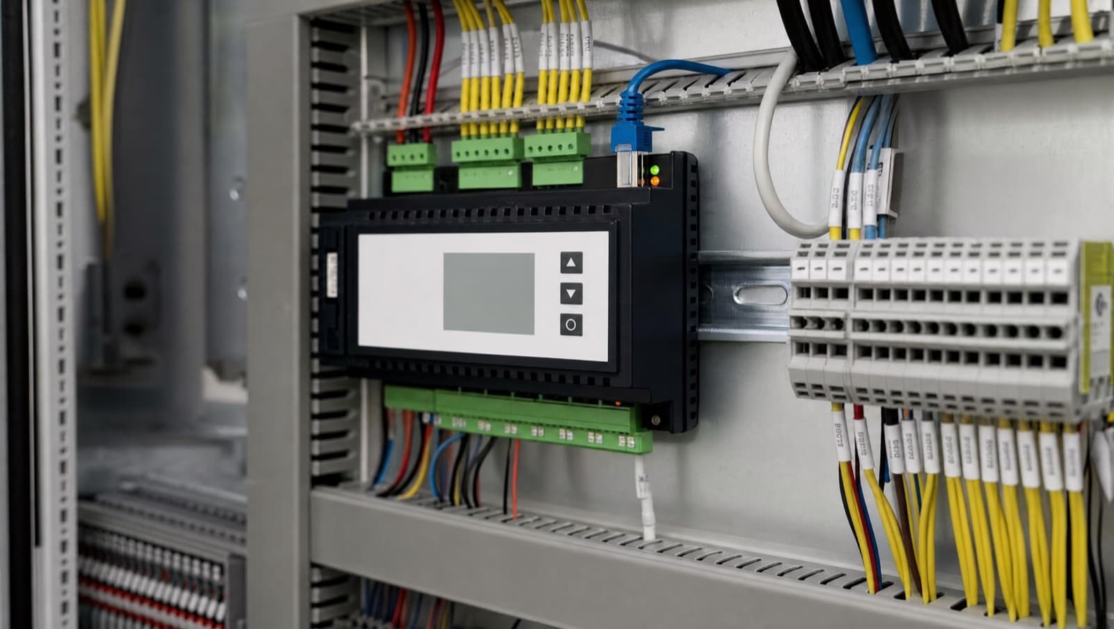
In a properly integrated data centre, the leak detection system feeds directly into the BMS via Modbus TCP. Each sensing cable zone is mapped to a BMS point that includes the zone identifier, the alarm state (normal, leak detected, cable fault, communication fault), and — for addressable systems — the measured leak position along the cable. The BMS processes these inputs alongside its existing environmental monitoring data: supply and return temperatures on the chilled water circuit, CRAC/CRAH unit status, room temperature and humidity at cabinet row level, and chilled water flow rates from the plant room.
This integration enables the BMS to do something that a standalone leak detection panel cannot: correlate the leak alarm with the facility state and execute a proportionate response. If a leak is detected on the chilled water supply to CRAC units serving rows 10-20, and the BMS knows that those units are running at 60% capacity with adjacent units available to pick up the load, it can sequence a controlled shutdown of the affected CRAC units while ramping up the adjacent units to maintain cooling coverage — all before the duty engineer has even received the SMS. That is not a theoretical scenario. It is exactly the kind of sequence-of-operations logic that a BMS is designed to execute, and it is the reason that leak detection without BMS integration is a fundamentally incomplete solution in a data centre.
For facilities that run a DCIM platform — Schneider EcoStruxure IT, Nlyte, Sunbird, or similar — the leak detection system also needs to feed into the DCIM via SNMP. This provides the data centre operations team with leak status on the same dashboard as power, cooling, and capacity data. The BMS handles the control response (valve sequencing, CRAC management, alarm escalation to the FM team), while the DCIM handles the operations visibility (dashboard alerts, incident logging, SLA impact assessment). Both systems need the data, and both need it in real time.
Alarm escalation in a data centre follows a stricter protocol than in a standard commercial building. A confirmed leak alarm should trigger simultaneous SMS and email alerts to the duty engineer, the facility manager, and the on-call M&E team within 30 seconds. The BMS alarm priority should be set to Critical — the highest tier — bypassing any acknowledgement delay and staying active until manually cleared at the panel after physical inspection confirms the leak is resolved. If the facility has a manned operations centre, the alarm should also appear on the NOC (Network Operations Centre) displays so that the IT operations team is aware of a potential environmental event affecting the compute floor. This entire escalation chain — from sensor to SMS to NOC screen — needs to be tested quarterly. If it has not been tested, it does not work.
What does a real data centre leak detection upgrade look like?
Alpha Controls was engaged by a colocation data centre operator in outer London to redesign and integrate the leak detection system across a 2,000 square metre raised-floor data hall with 450 cabinets, served by eighteen CRAC units on a chilled water circuit fed from roof-mounted chillers.
The existing installation had TraceTek sensing cable under the raised floor, installed during the original fit-out four years earlier. The cable covered approximately 70% of the under-floor area in a grid pattern, but it did not specifically follow the chilled water pipe runs — which had been modified twice since the original installation as cooling capacity was expanded. Several cable sections had been damaged during floor tile removal for under-floor cabling work and had never been repaired. The detection panel was a standalone unit in the electrical switchroom, not connected to the BMS (a Trend IQ4 system) or the DCIM platform. Alarm output was via a local sounder and a single email address that went to a shared FM mailbox. There was no automatic shut-off capability and no defined escalation protocol.
We carried out a full survey of the under-floor environment, mapping all chilled water pipe routes, condensate drain runs, and CRAC unit positions against the existing cable layout. We then designed a replacement installation using TTK FG-NET addressable cable, routed specifically along every chilled water pipe run, looped around every CRAC unit base, and extended into the riser shaft where the CHW mains entered the data hall from the roof plant. Condensate monitoring was added at the overflow point of every CRAC drip tray, using point sensors connected to the same FG-NET controller.
The FG-NET controller was integrated into the Trend IQ4 BMS via Modbus TCP, with each cable zone mapped to a BMS monitoring point. We programmed alarm escalation logic in the BMS: a confirmed leak alarm on any zone triggers an immediate SMS to the duty engineer and facility manager, an email to the operations team, and a Critical priority alarm on the Trend TONN supervisor. For zones serving specific CRAC unit pipe runs, we programmed conditional shutdown sequences that close the motorised isolation valve on the affected pipe section while the adjacent CRAC units ramp up to compensate — maintaining cooling coverage to the cabinet rows while isolating the water source.
The DCIM platform received leak status via SNMP from the FG-NET controller, providing the NOC team with dashboard visibility alongside power and cooling metrics.
The total installation took three weeks of night shifts — all work carried out outside core operational hours to maintain the facility's SLA commitments. The system was commissioned with full water-on-cable testing at twelve positions across the data hall, confirming location accuracy, alarm response time, and end-to-end escalation including SMS delivery.
What does a properly designed data centre leak detection system look like?
A properly designed data centre leak detection installation has characteristics that go well beyond the sensor layout.
The cable follows the water. Every chilled water pipe run, every condensate drain route, every valve assembly, every riser penetration has sensing cable routed along it — not in a generic grid pattern that hopes to catch water as it spreads, but tracing the exact paths where water will appear first when something fails.
Condensate is monitored independently. Every CRAC and CRAH unit drip tray has either sensing cable around its perimeter or a point sensor at the overflow point. Condensate drain runs are monitored at low points where blockages are most likely to cause overflow.
The detection panel has no single point of failure. Dual power supply — mains plus UPS-backed circuit. Battery backup at the panel level. Dual communication paths to the BMS and DCIM. If any one of these elements fails, the system continues to operate and the failure itself generates an alarm.
Integration is complete. The BMS receives zone-level alarm data via Modbus TCP and can execute automated responses — valve isolation, CRAC sequencing, alarm escalation. The DCIM receives the same data via SNMP for operational visibility. Both systems are tested together during commissioning.
Automatic shut-off is zone-based, not facility-wide. Motorised isolation valves are installed on each branch of the chilled water distribution, so that a leak on one pipe run can be isolated while the rest of the cooling circuit continues to operate. The BMS manages the valve sequencing and the CRAC load redistribution as a coordinated response.
Alarm escalation is defined, documented, and tested. SMS, email, BMS alarm, DCIM dashboard, NOC display — all triggered within 30 seconds of a confirmed leak event. Tested quarterly with documented results. For an understanding of how this fits into the broader BMS picture, our post on what a building management system is explains the control and monitoring framework that leak detection integrates into.
When should you act on data centre leak detection?
If your data centre has leak detection that was installed during the original fit-out and has not been surveyed since, the cable layout almost certainly does not match the current pipe routes. Cooling infrastructure evolves — CRAC units get added, pipe runs get extended, risers get modified — and the detection system needs to evolve with it. A survey and re-route is significantly cheaper than a single leak event.
If your leak detection panel is a standalone unit with no BMS or DCIM integration, you have a system that detects leaks but cannot respond to them intelligently. A panel alarm in an unmanned switchroom at 2am is not a detection strategy. Integration into the BMS and DCIM, with automated alarm escalation and — where appropriate — automated valve isolation, is the minimum standard for any facility operating above Tier I.
If you are designing a new data centre or expanding an existing one, specify the leak detection and BMS integration as a single package from a single contractor. The interface between the two systems — the Modbus mapping, the alarm logic, the valve sequencing, the escalation protocols — is where most installations fail, and it fails because the detection contractor and the BMS contractor are different companies with no shared specification. Alpha Controls delivers both, which eliminates that interface risk entirely.
For the broader picture on UK leak detection standards and insurance requirements that apply to data centres as well as commercial buildings, our companion post on leak detection standards and insurance in the UK covers BS 8558, FM Global, LPCB, and the insurer landscape in full detail. And for the specific challenges of plant room leak detection — which applies to data centre plant rooms as much as any other facility — our post on leak detection in plant rooms is directly relevant.
The bottom line on data centre leak detection
Data centres are the highest-risk environment for water damage in any commercial building portfolio, and leak detection in a data centre demands a level of design rigour, integration depth, and maintenance discipline that goes well beyond what works in a standard office or retail building. EN 50600 and the Uptime Institute Tier Standard both require it. Insurance underwriters expect it. And the financial consequences of getting it wrong — hardware destruction, SLA breach, client loss — make the investment case overwhelming.
Alpha Controls designs and installs BMS systems for data centres and integrates leak detection as part of the same environmental monitoring and control package. One contractor, one specification, one commissioning process — with the detection, the BMS logic, the valve sequencing, and the alarm escalation all designed and tested together. If your data centre needs leak detection installed, upgraded, or properly integrated into the BMS, see our leak detection and trace heating service, then get in touch or request a quote and we will scope it properly.
Alpha Controls
Specialist BMS installation, commissioning, and maintenance across London and the South East. SafeContractor Approved, BCIA Member.