
A Trend IQView4 that won't power up has, in our experience, usually lost its 24 V supply rather than failed. The display needs its own 24 Vac or 24 Vdc feed — Trend say the controller's auxiliary output can't be relied on for it. So work the chain: transformer secondary, transformer primary, then the circuit feeding it. Then start suspecting the device.
The call was "the IQView4 is down". What we found was the whole BMS off — controller as well as display. The screen was just the part you can see without opening the panel.
The cause was a UPS sitting inside the panel, feeding one of three control transformers, which had failed. A label on the door named the UPS. Nothing in the panel said which transformer ran through it, so the supply had to be traced conductor by conductor. Nine hours.
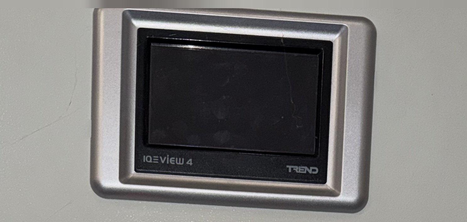
What the call was about. Behind this door the controller was dark too, but the plant carried on running and indicating on its hard-wired lamps — so from outside, a blank screen was the whole fault.
Safety. This job involved 230/400 V inside a live panel, transformer primaries, and a UPS — which is a second source, so isolating the panel doesn't necessarily kill everything in it. Everything was tested and proved, and the alteration was done dead. Don't work like this unless you're competent to and following the site's safe systems of work.
Why won't a Trend IQView4 power up?
Because it's a 24 V device on the end of a supply chain, and something in that chain has gone. Trend's installation instructions (IQView4 Touch Screen Display Installation Instructions, TG201038, Issue 10) call for 24 Vdc ±15 % at 3 W, or 24 Vac ±10 %, 50/60 Hz at 8 VA, and say the required power "cannot be guaranteed to be provided from an IQ controller's auxiliary supply output; a separate supply is generally required". Same document: don't use a centre-tapped-to-earth transformer on it.
That separate supply is what makes the dark screen useful. It tells you the 24 V has gone or the device has died. Prove the supply before you condemn the display. The display talks to the controller over RS232 on the local supervisor port, so on its own it says nothing about whether the controller is faulty.
In our case it wasn't faulty. It wasn't running either. Photos before the re-feed show the IQ3 controller and all five I/O modules dark; fifteen minutes later, supply back, every one of them lit. Nothing had failed. Both had been switched off by something two steps upstream.
The clue was on the panel door
Before any covers came off, we read the fascia. Next to a yellow "24V AC" label was this:
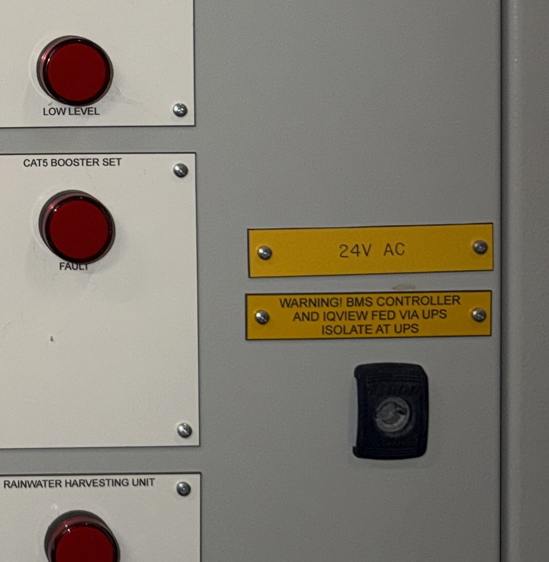
"WARNING! BMS CONTROLLER AND IQVIEW FED VIA UPS — ISOLATE AT UPS". Whoever fitted this did the next engineer a favour: it's what put the UPS in the frame. What it doesn't say is which of the three control transformers is the one fed through it.
That label exists because BS 7671 Regulation 514.15 wants a warning notice wherever there's an additional source of supply — at the origin, at the board it connects to, and at every point of isolation. A UPS in a control panel is exactly that. On an inherited system a label can be more accurate than the drawings, because whoever did the work put it there.
Finding one sheet in a 300-page pack
There was a drawing pack on site, roughly 300 pages of it. Size isn't the problem — finding the right sheet is. The one that mattered showed the IQView4, its 24 V and 0 V terminals, the cable reference carrying them, and the RS232 run back to the controller.
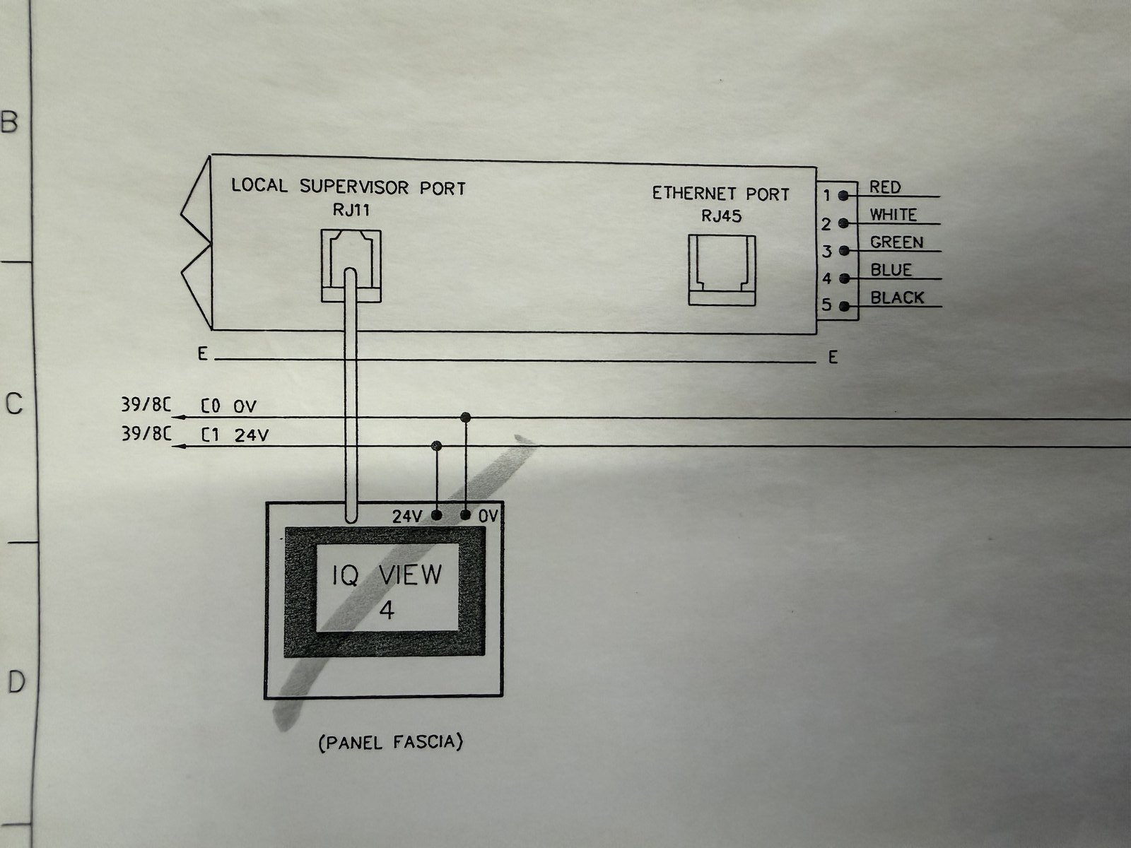
The sheet worth finding: IQView4 in the fascia, 24 V and 0 V identified by cable reference, RS232 to the controller's local supervisor port. That cable reference is what made the rest of the day possible.
Keep the pack indexed and keep it at the panel, not in an office three buildings away. Same argument we make about points lists and I/O schedules: the document only earns its money if the bloke at 2am can find the line he needs.
Get a Free BMS Survey
We'll assess your controls and provide a detailed quotation.
Three identical transformers, one dead
Three PES 100 VA units, 240 V in, 24 V out, 0.41 A primary, to BS EN 61558-2-4, side by side on the same gear plate. Nothing to tell them apart.
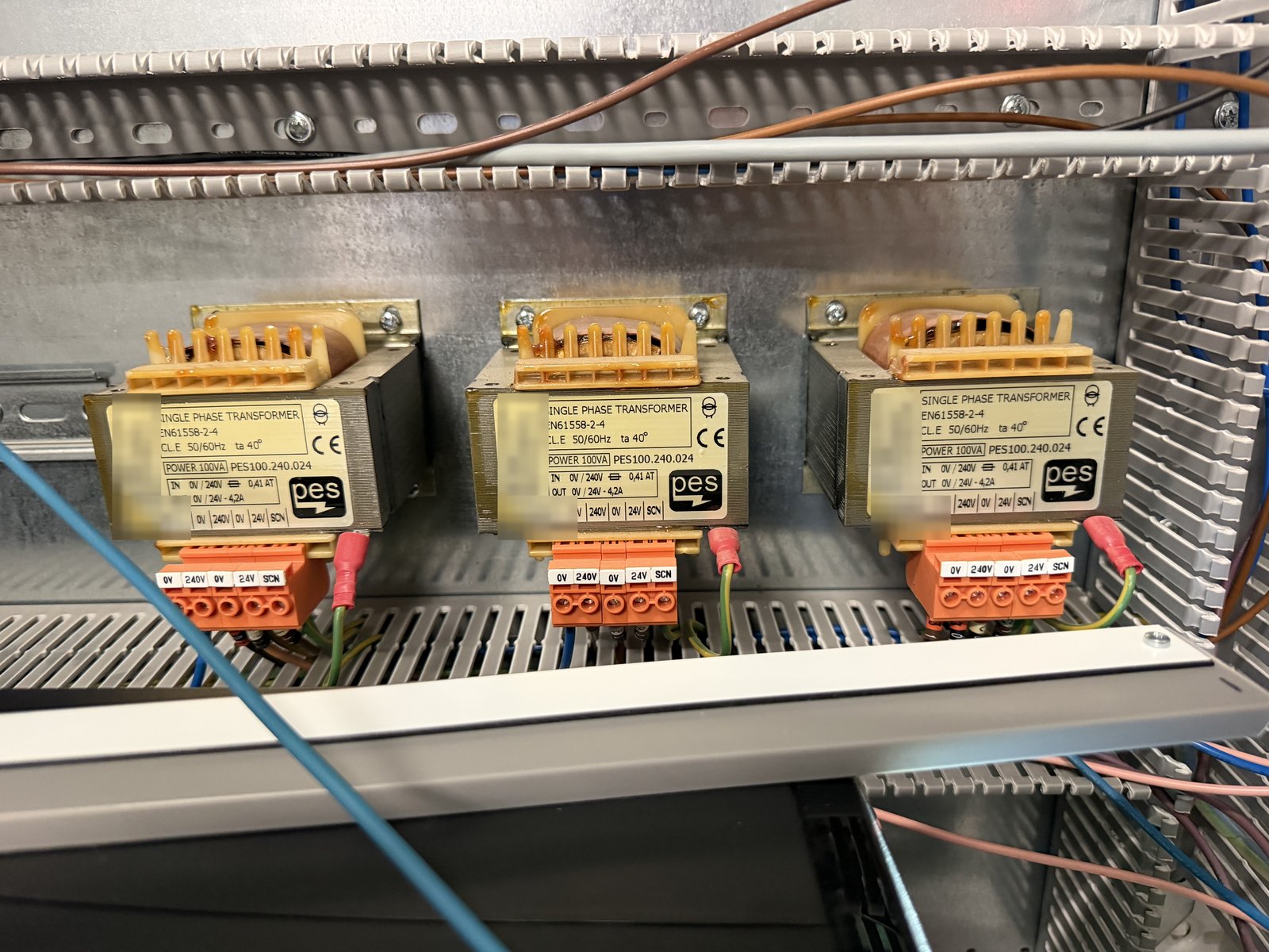
Three 100 VA 240/24 V control transformers, identically specified and identically terminated. Nothing visible marks out the one fed from a different source to the other two.
Testing at the primaries sorted them out fast. Two healthy. The third read 0.145 V AC.
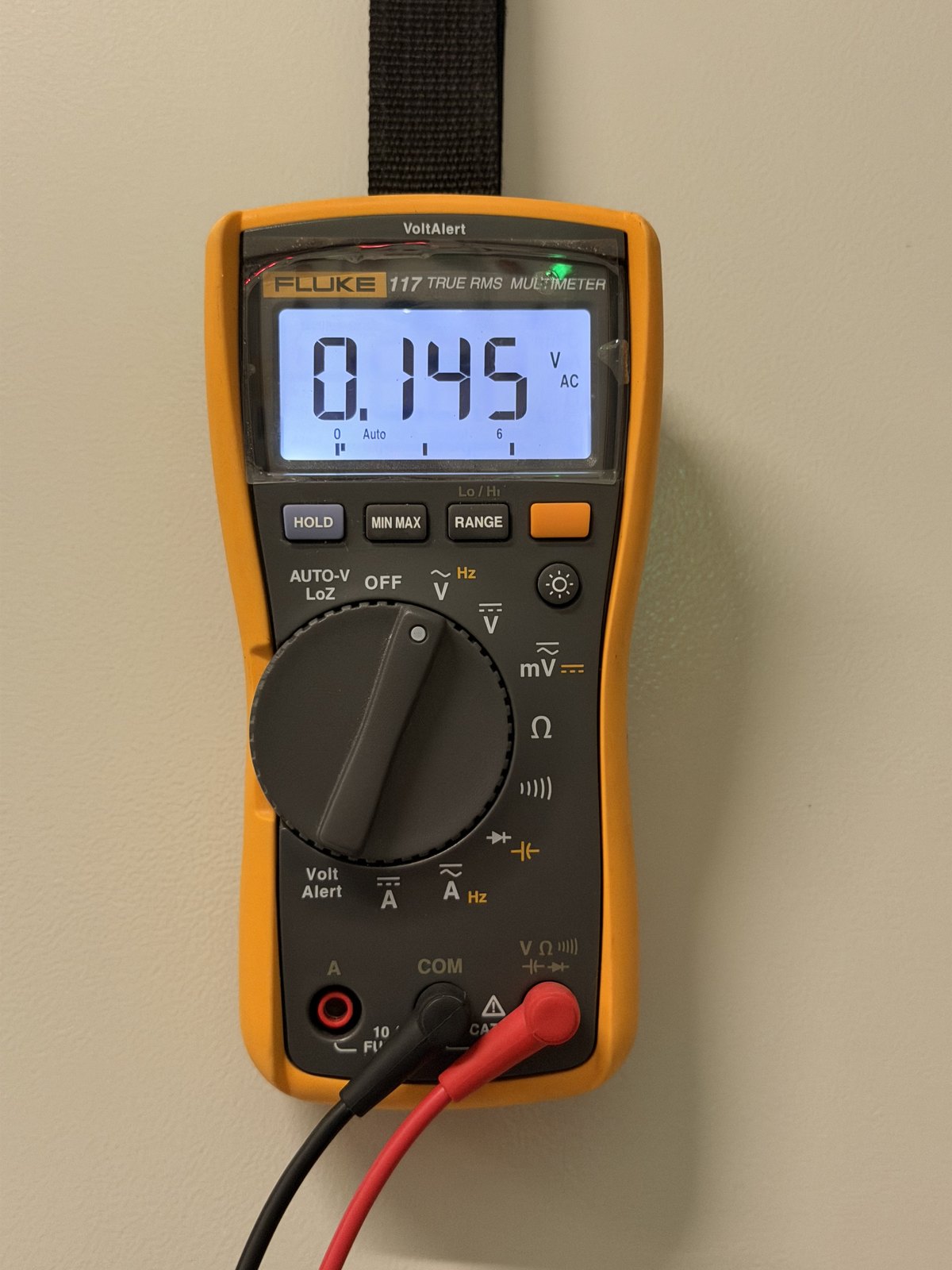
0.145 V AC at the primary of the transformer feeding the BMS. The photo records the reading; the probes were at the primary terminals, below frame. The other two measured about 250 V AC at the same point.
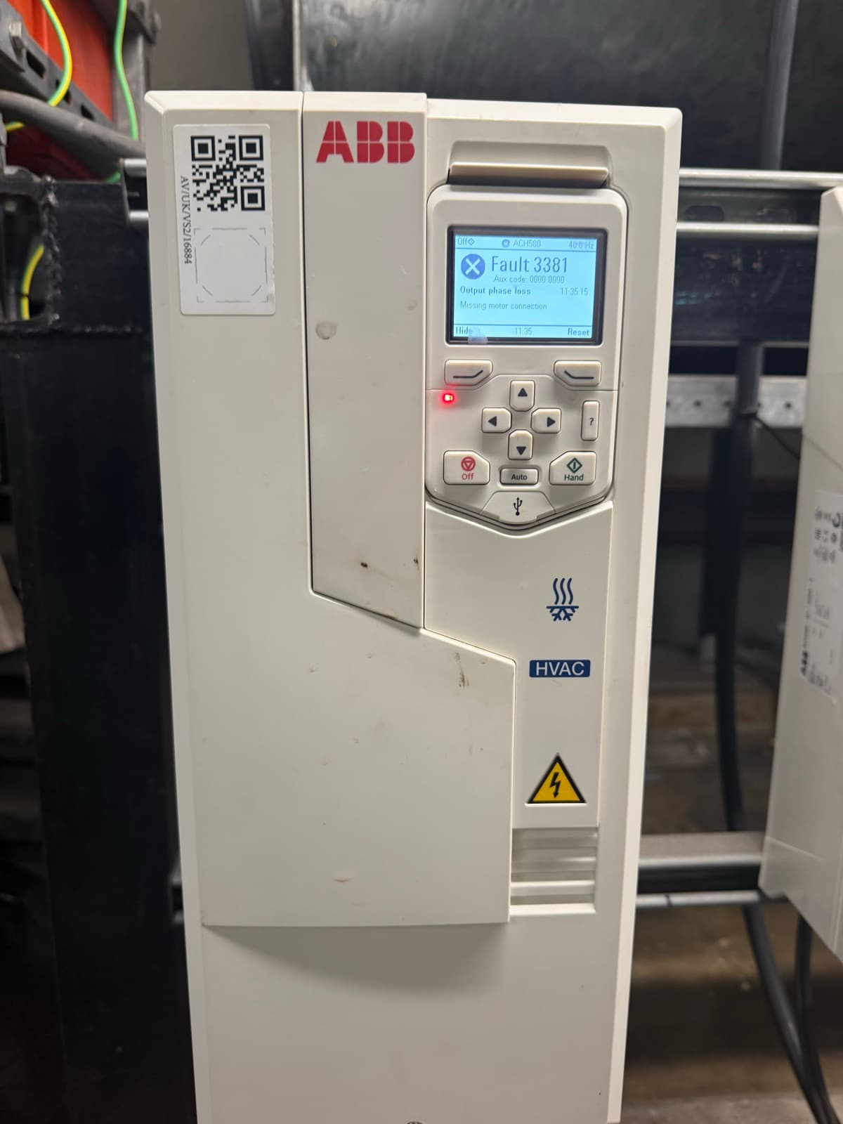
Be careful what you take from that number. With two healthy transformers beside it, it tells you there's no usable supply at that primary and the fault is upstream. It doesn't prove the mechanism. A fraction of a volt on a high-impedance meter is commonly induced voltage on a disconnected conductor, but if you want to know rather than assume, take a loaded or LoZ reading. Same discipline as the ABB drive we traced to motor terminal links rather than a dead drive: prove the supply before condemning the device.
What it does not tell you is whether the transformer itself is any good. It tells you nothing is reaching it. That distinction matters, because "no 24 V at the secondary" gets answered with a van-stock swap — and if the supply is the problem, the fault's still there afterwards. On this job the transformer energised normally once it was re-fed, which is what established that this one was serviceable. The meter reading never did.
No schedule, so trace it
Next step should have been quick: open the circuit schedule, read which breaker feeds that transformer. There wasn't one in the panel.
Regulation 514.9.1 asks for a diagram, chart, table or equivalent — and one of the things it has to convey is the information needed to identify the devices doing protection, isolation and switching. That's precisely what nobody could do here.
So we traced by hand. The two working transformers came off individual MCBs. The third took a different route, and that route ended at the UPS on the floor of the panel.
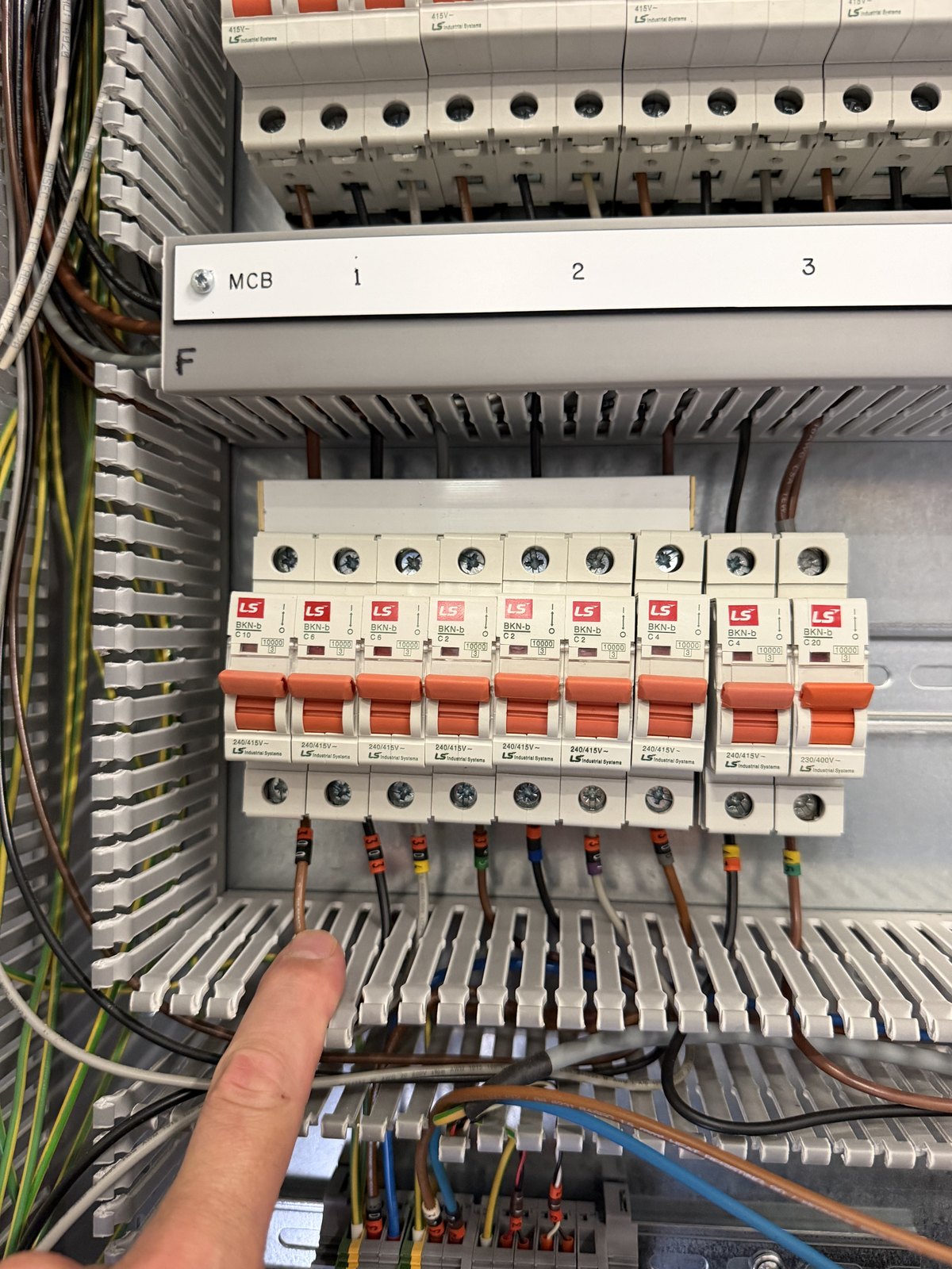
The MCB row. Two of the three transformers fed from here. Without a schedule, working out which breaker did what meant following conductors.
Anyone who's inherited a legacy system knows this one. It's the same cost that turns up in every end-of-life panel upgrade: the hours aren't in the work, they're in finding out what's already there.
The UPS: mains in, nothing out
Fault code A62. About 250 V AC at its input, nothing coming out. That closed it — the transformer had no primary supply because the thing feeding it had failed while still looking, to anyone glancing at the panel, perfectly alive.
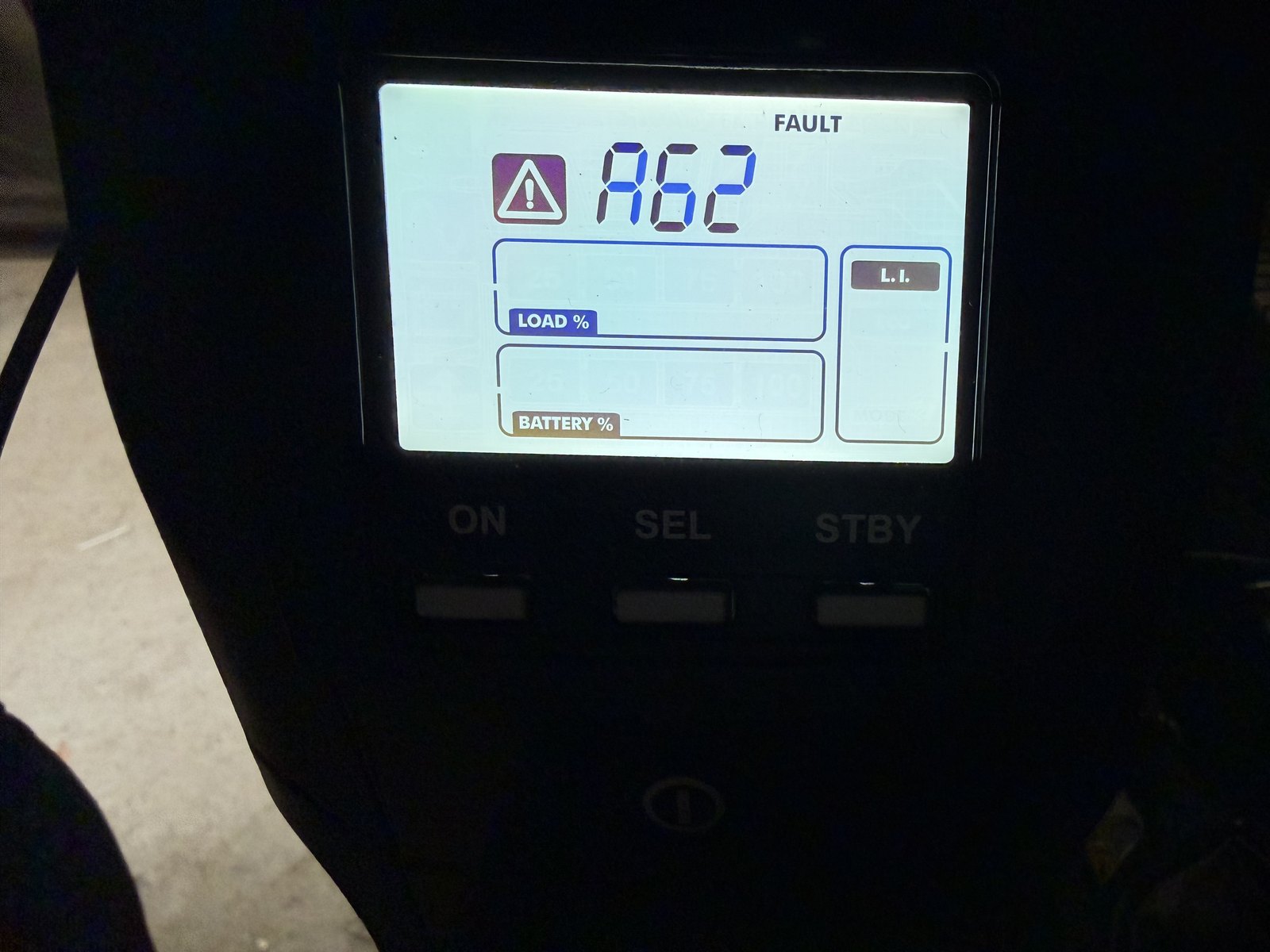
The UPS in fault: code A62, no load, no battery indication. Mains present in, nothing out. Refer any code to that manufacturer's manual — the useful bit here is "mains in, nothing out", not the number.
A UPS on a BMS panel is a fair design call. A controller that rides through a short interruption doesn't drop its plant, lose its clock or come back mid-strategy. The problem here wasn't the UPS — it was how little of it was traceable. The door label named it; nothing tied it to a circuit. We saw no monitored fault contact wired back to the BMS. We never saw the site's maintenance records or asset register, so we can't speak to those.
If you fit one, wire its fault and battery contacts into spare digital inputs. No monitoring catches everything, and we can't say it would have caught this — but a device that reports its own condition gives you a chance of an alarm. An unmonitored one gives you none. Same argument as reactive versus planned maintenance.
The fix
The affected transformer is 100 VA, about 0.41 A at 240 V. A C10 breaker in the panel already fed a local double socket. We proposed re-feeding from that, the office agreed, and then it was done: UPS bypassed for this supply only, line onto the C10 circuit, neutral across to the neutral bar.
The UPS itself was left energised off its own incoming mains. What changed is that it no longer feeds this transformer.
Three things worth saying, because load arithmetic on its own doesn't make an alteration right. Conductor and overcurrent coordination needs checking, not assuming. Altering a fixed installation is certifiable work — Alpha Controls installs to BS 7671, we're not NICEIC registered, and where a job needs certification only a registered contractor can issue, we arrange it through one. And the BMS now shares a socket-outlet circuit, which is normally RCD protected, so an earth fault in something somebody plugs in can take the controller down. Fine as a same-day fix to get the site seeing its plant again. Not what you'd choose permanently.
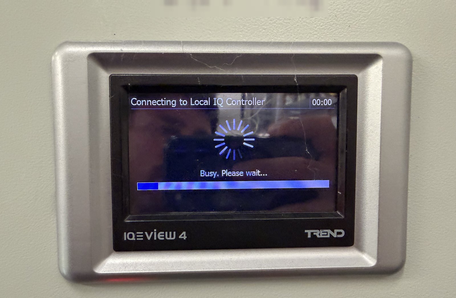
Supply back, display up, connecting to the local IQ controller. The controller came back with it — neither had failed, both had simply been off.
What we left, and what we took off the door
The UPS is still faulty and still needs repairing or replacing. And somebody needs to confirm whether UPS-backed operation was ever a design requirement. If it was, this arrangement goes back when the UPS is sorted. If it wasn't, accept it formally and update the drawings.
One thing didn't wait. The engraved "ISOLATE AT UPS" notice came off the panel before we left. The moment that transformer came off the UPS, the notice stopped describing the supply it pointed at — and a notice describing a supply that doesn't exist is worse than no notice, because people act on it. Isolate at the UPS on the strength of it and you'd think the control supply was dead when it's live off the C10.
Be careful what you conclude about isolation from any of this. Trace and prove every incoming source before you treat a panel as dead. On this attendance the UPS input remained energised, and we did not establish the source or isolation relationship of that UPS supply — so nothing here says the enclosure has a single point of isolation. What we did establish is that the BMS control supply no longer runs through the UPS, which is why a notice sending the next engineer there had to come off. The label and the wiring have to tell the same story before you leave, and neither of them is a substitute for proving dead at the point of work.
Worth taking away
Work the supply path before you condemn a dead IQView4 — it runs on its own 24 V feed, so prove that first. Prove the primary before condemning a transformer — 0.145 V against 250 V on the two beside it tells you the supply is missing, not that the transformer is good. Only re-feeding it showed that. Read the panel labels before the drawings. And a missing circuit schedule costs real hours, which is what 514.9.1 exists to prevent.
We do BMS callouts, fault investigation and panel remedials across London, Kent and the South East — Trend, Distech, Siemens, Schneider, and plenty of installations nobody has the history for. A panel nobody fully understands is a normal starting point, not an awkward admission. Get in touch or ask for a quote.
Evidence notes. One Alpha Controls callout, recorded as a nine-hour attendance. Site, client and main contractor aren't identified, and the original panel manufacturer's title block is off the drawing image. The readings quoted (0.145 V AC at the affected primary, about 250 V AC at the others and at the UPS input) are what was measured on that job, not general reference figures. The UPS fault code is the code that unit displayed.
Sources. Trend Control Systems, IQView4 Touch Screen Display Installation Instructions TG201038, Issue 10, 29-Aug-2018. BS 7671:2018+A2:2022, Regulation 514.9.1 (information identifying devices performing protection, isolation and switching) and Regulation 514.15 (warning notices where additional sources of supply are present). BS EN 61558-2-4, as marked on the installed transformers.
Alpha Controls Team
Specialist BMS installation, commissioning, and maintenance across London and the South East. SafeContractor Approved, BCIA Member.