
A six-terminal three-phase motor has three windings brought out as pairs: U1–U2, V1–V2 and W1–W2. Connect it in star by bridging U2, V2 and W2 together and feeding the supply to U1, V1, W1; connect it in delta by linking U1–W2, V1–U2 and W1–V2 and feeding the supply to the three linked pairs. Which one you use is dictated by the nameplate: a motor marked 400/690 V Δ/Y runs in delta on a UK 400 V supply, and a motor marked 230/400 V Δ/Y runs in star.
Most engineers can recite that. Fewer can say why the studs are arranged the way they are, why one motor's links are three vertical strips and another's are a single bar, or what the drive actually sees when the links are wrong. The last question is not academic. On a callout this summer we found a 15 kW Brook Crompton fan motor whose delta links had been rearranged during earlier works, and the ABB ACH580 feeding it was tripping Fault 3381 — Output phase loss / Missing motor connection on every start with three healthy phases and three healthy windings. The full investigation is in our case study tracing an ABB ACH580 Fault 3381 to incorrect motor connections. This article is the reference we would hand to anyone about to open a motor terminal box.
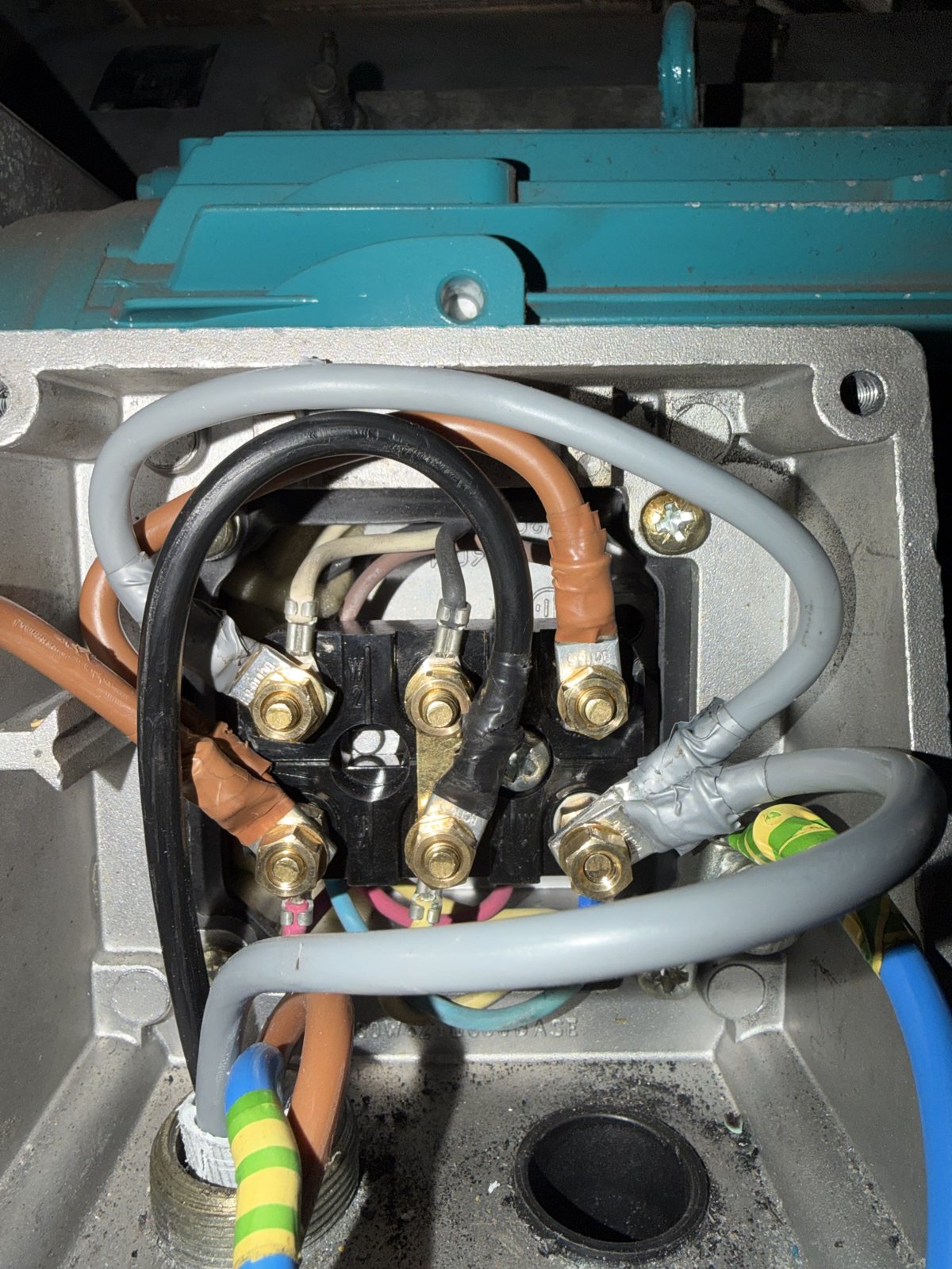
The six-stud terminal board of the 15 kW Brook Crompton motor from the case study, photographed during reconnection. Vertical brass links join each top stud to the stud below it — the delta arrangement for this board.
Safety. Motor terminal boxes carry three-phase low voltage and, on inverter-fed motors, conductors that remain hazardous until the drive's DC bus has discharged. Isolate, lock off and prove dead with GS38-compliant equipment before removing the lid. Connection changes are work for competent persons under the Electricity at Work Regulations 1989, and the connection diagram supplied with the motor takes precedence over anything written here.
What do U1, V1, W1, U2, V2 and W2 mean on a motor?
The letters are the three phases of the motor — U, V and W — and the numbers are the two ends of each winding. U1–U2 is one complete winding, V1–V2 the second, W1–W2 the third. The “1” end is conventionally the start and the “2” end the finish, and the markings, the winding sense and the direction convention that goes with them are defined in BS EN / IEC 60034-8, Rotating electrical machines — Terminal markings and direction of rotation. That standard is why a Brook Crompton motor, a Siemens motor and a WEG motor all present the same six markings, and why the supply lines L1, L2, L3 connected to U, V, W in order give clockwise rotation viewed from the drive end.
Bringing both ends of every winding out to the terminal board is what makes the motor dual voltage. The links you fit in the box decide how the three windings are joined, and therefore what voltage each winding sees for a given supply. Three-terminal motors with the connection made internally exist — small single-voltage machines, some hazardous-area designs — and cannot be reconnected, but the general-purpose IEC motor on a fan or pump has six studs and expects you to make the choice.
What is the difference between star and delta?
In star (Y, sometimes “wye”), the three winding finishes are joined at a common star point and the supply feeds the three starts. Each winding sits between one line and the star point, so it sees the line voltage divided by √3: on a 400 V supply, about 230 V per winding.
In delta (Δ), the finish of each winding is joined to the start of the next, forming a closed triangle, and the supply feeds the three corners. Each winding sits directly between two lines and sees the full line voltage: 400 V per winding on a 400 V supply.
Same motor, same supply, different winding voltage by a factor of √3 — and because torque follows the square of winding voltage, a motor that should be in delta but has been connected in star develops roughly a third of its rated torque. That is the physical fact underneath every star/delta decision.
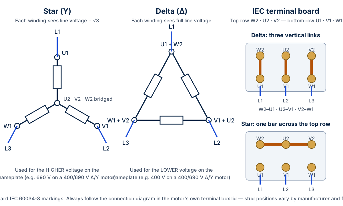
Star and delta as circuits, and as they appear on a standard IEC terminal board. The staggered stud layout is deliberate: delta becomes three vertical links, star becomes one bar across the top row.
How are the six terminals laid out, and where do the links go?
Look at the board rather than the wiring and the layout explains itself. The usual arrangement on an IEC-marked six-terminal board — a manufacturers' convention rather than a clause of the standard, which covers the markings and the direction rule — puts W2, U2, V2 across the top row and U1, V1, W1 across the bottom. The top row is rotated one place relative to the bottom, so that each top stud sits directly above the stud it needs to be joined to for delta:
- Delta: three vertical links — W2–U1, U2–V1, V2–W1 — with L1, L2, L3 landed on U1, V1, W1.
- Star: one bar (or two links) across the top row joining W2–U2–V2, with L1, L2, L3 on U1, V1, W1 as before.
The supply lands on the bottom row in both cases. Only the links move. That is the whole point of the layout, and it is why a set of three vertical brass strips in a UK motor terminal box almost always means “delta” before you have read a single marking.
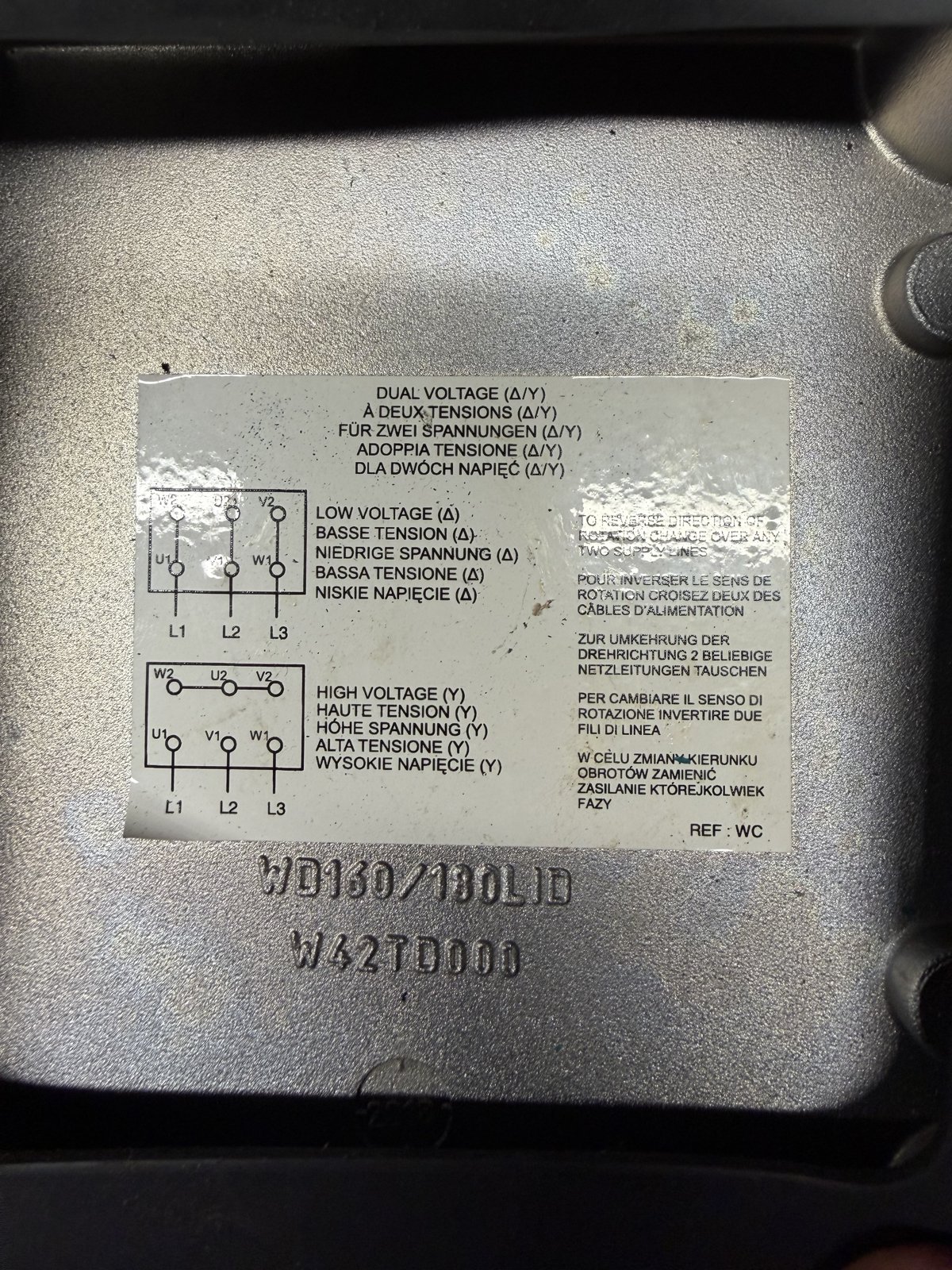
The manufacturer's own diagram, inside the lid of the case-study motor's terminal box: LOW VOLTAGE (Δ) with three vertical links, HIGH VOLTAGE (Y) with the top row bridged, and “to reverse direction of rotation change over any two supply lines”. This label, not a general diagram, is the authority for that motor.
The manufacturer's diagram overrides the generic one. Brook Crompton's Installation & Maintenance sheet 103-4E says plainly: “The connection diagram is shown on the leaflet enclosed in the motor terminal box or the diagram inside the terminal box lid”, and “refer to the connection diagram supplied with the motor for supply details and the required winding connection”. Some manufacturers use a different stud order; some older or rewound motors have been re-marked. The diagram in the lid is what the winding actually does.
Get a Free BMS Survey
We'll assess your controls and provide a detailed quotation.
How do you read the voltage on a three-phase motor nameplate?
A dual-voltage nameplate gives two voltages separated by a slash and two connection symbols in the same order. The lower voltage always goes with delta and the higher with star, because star puts the windings across √3 less voltage. The two current figures follow the same order.
| Nameplate marking | Meaning | On a UK 400 V three-phase supply |
|---|---|---|
| 230/400 V Δ/Y | Delta at 230 V, star at 400 V | Star. Typical of small motors, roughly 3 kW and below. |
| 400/690 V Δ/Y | Delta at 400 V, star at 690 V | Delta. Typical of 4 kW and above, and the only marking that permits a star-delta start on 400 V. |
| 400 V Δ (single voltage) | Delta only; may have three or six terminals | Delta. If six terminals, links as delta; do not run in star. |
| 28.3/16.4 A alongside 400/690 V | Line current in delta at 400 V, then in star at 690 V | The delta figure is the one the overload or drive should be set to on 400 V. |
The Brook Crompton plate from the case study is a worked example: WP–DA160LU–IE3, 15.0 kW, 400/690 V Δ/Y, 28.3/16.4 A, 1475 r/min at 50 Hz. On the site's 415 V supply that motor belongs in delta with 28.3 A as its full-load current, which is what the drive's motor data should carry. Brook Crompton's W-range literature follows the convention in the table — up to 3 kW wound 230/400 V, 4 kW and above 400/690 V — but the rule of thumb is the fallback; the plate is the instruction.
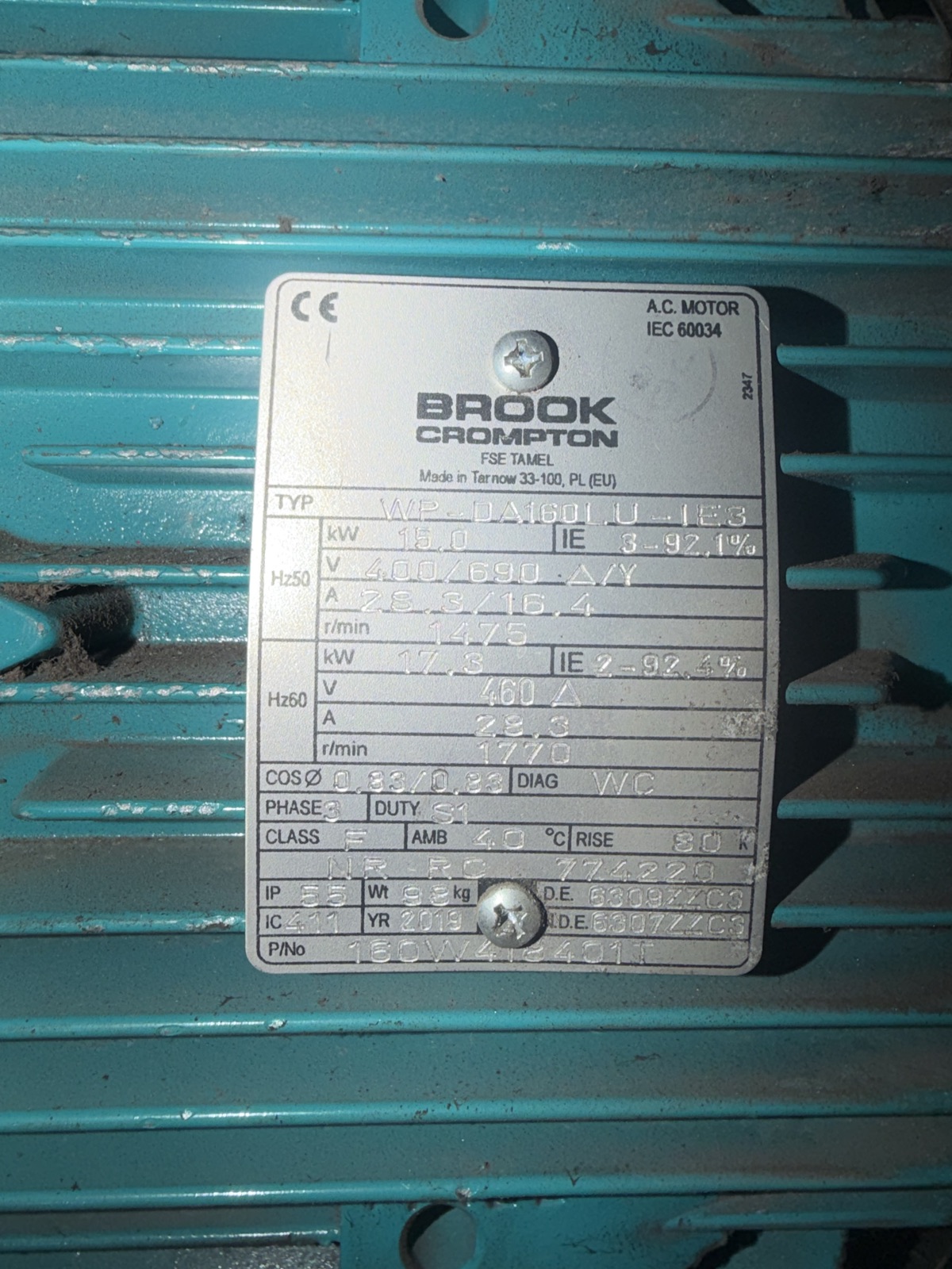
The nameplate from the case study. Two voltages, two symbols, two currents, all in the same order: delta at 400 V drawing 28.3 A, star at 690 V drawing 16.4 A.
Is a fixed star or delta connection the same as a star-delta starter?
No, and confusing the two causes real damage. A fixed connection is what this article has described so far: links fitted once in the terminal box, three supply conductors, and the motor runs in that configuration permanently. Direct-on-line starters and variable speed drives both feed a fixed connection.
A star-delta starter is a starting method. There are no links in the terminal box at all; six conductors run from the starter to the six studs, and a set of contactors connects the windings in star for the first seconds of the start — drawing roughly a third of the delta starting current — then switches them to delta for running. It only works on a motor whose delta voltage matches the supply, so on 400 V it needs a 400/690 V motor. A 230/400 V motor cannot be star-delta started on 400 V; it would run in delta at nearly twice its winding voltage.
The practical consequences: if you find six conductors and no links, do not “tidy it up” by fitting links — with delta links fitted, the moment the starter's star contactor closes it puts a line-to-line short across the supply. If you find a star-delta starter being replaced by a VSD, the six-core cable becomes three cores plus links (delta, on a 400/690 motor) and the drive takes over current limiting; the AHU-2 job written up in our inverter replacement article is the kind of project where that decision gets made. And if you need to reverse a star-delta-started motor, swap two incoming lines at the starter, not two of the six motor conductors — our guide on how to reverse a three-phase motor on an AHU fan explains why.
What happens when the links do not match the motor and the supply?
Three failure modes, in increasing order of subtlety.
A 400/690 V motor connected in star on 400 V sees 230 V per winding. Starting torque collapses to about a third, the motor may not accelerate a loaded fan or pump, it runs slow and hot, and on a VSD you get overload, stall or motor-overtemperature trips rather than a clean fault. It is the commonest wrong connection because “star is safer” is a half-remembered rule from starters.
A 230/400 V motor connected in delta on 400 V puts 400 V across windings designed for 230 V. The magnetising current rises steeply, the motor saturates and overheats, and the insulation fails in hours or days. Overload protection set to the delta current on the plate will not save it because that figure was for a 230 V supply.
An arrangement that is neither star nor delta — a link missing, a link across the wrong pair, a supply core landed on a “2” terminal — produces an unbalanced circuit that a contactor will happily energise and a drive will refuse. This is what we found in the case study. The individual windings each measured about 0.5 Ω once the links were removed, balanced within the tolerance of a handheld meter, but connected as found the phase-to-phase readings were inconsistent and near zero on two pairs. The ACH580's output current sensing could not see three normal phases and reported 3381 Output phase loss — ABB's own description is “motor circuit fault due to missing motor connection (all three phases are not connected)”. The code was accurate from the drive's point of view and useless as a diagnosis until someone opened the box.
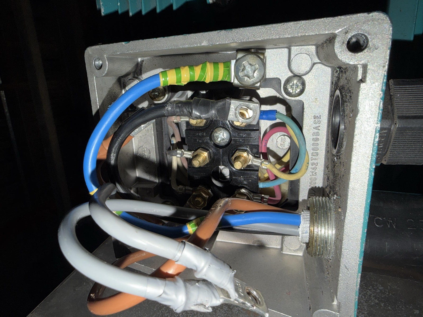
Links removed and supply tails taped back on the case-study motor, so each of the three windings could be measured on its own. Connected links hide open windings and mask link errors; separated windings make balance visible.
How do you check a motor's connection before you energise it?
Start at the lid. Read the connection diagram and the nameplate, decide which configuration the supply requires, and only then look at the studs. Count the links and confirm each one joins the pair the diagram shows; on an IEC board delta is three verticals and star is one horizontal bar, and anything else needs explaining. Confirm the supply cores are on U1, V1, W1 and that the earth is on the earthing terminal in or beside the box — Brook Crompton is explicit that an earth bond “should not be terminated under the motor fixture bolts or terminal cover screws”. Check that terminal nuts are torqued to the manufacturer's table, with lugs in face-to-face contact and no washers between them.
With the motor isolated from its drive or starter, two electrical tests are worth doing, and worth stating the limits of. Winding resistance, measured with the links removed so each winding is independent, should be balanced across the three; on the case-study motor all three read within 0.1 Ω of each other on a Fluke 117, and the neighbouring standby motor read the same, which is a far more useful reference than a table value. Insulation resistance to earth, with an insulation tester and never through a connected drive, tells you whether the winding insulation has broken down. Neither test proves the motor is healthy on its own: resistance says nothing about insulation, insulation resistance says nothing about a shorted turn or a bearing, and neither says anything about how the motor behaves under load. They rule out specific failures; they do not certify the machine.
Finally, make the drive agree with the connection. The nominal voltage and current entered in the drive's motor data (parameter group 99 on ABB's ACH580) must be the figures for the configuration actually fitted — 400 V and 28.3 A for the case-study motor in delta, not the star figures. A drive told to expect 16.4 A on a motor wired to draw 28.3 A will protect the wrong machine.
Frequently asked questions
How do I know whether to connect a three-phase motor in star or delta?
Match the supply voltage to the nameplate. The lower voltage on the plate goes with delta, the higher with star. On a UK 400 V supply a 400/690 V motor is connected in delta and a 230/400 V motor in star. If the plate shows one voltage only, that is the only permitted configuration.
What are the delta links on a six-terminal motor?
On a standard IEC board with W2, U2, V2 over U1, V1, W1, delta is three vertical links: W2–U1, U2–V1 and V2–W1, with the supply on U1, V1 and W1. Always confirm against the diagram in the terminal box lid, because stud layouts vary.
What happens if a 400/690 V motor is wired in star on a 400 V supply?
Each winding sees about 230 V instead of 400 V and the motor develops roughly a third of its rated torque. It may fail to start under load, run slow and hot, and trip a drive on overload or stall. It will not be damaged instantly, but it cannot do its job.
Can wrong motor terminal links cause a VSD output phase loss fault?
Yes. An arrangement that is neither a proper star nor a proper delta gives the drive an unbalanced output circuit. In our case study an ABB ACH580 tripped Fault 3381 Output phase loss on every start until the delta was restored, with no fault in the drive, the cable or the windings.
Is a star-delta starter the same as connecting the motor in star or delta?
No. A star-delta starter runs six conductors to the motor and switches the windings from star to delta itself during starting; there are no links in the terminal box. A fixed star or delta connection uses links and three conductors, and is what a DOL starter or a VSD feeds.
Motor, drive or BMS fault-finding across London, Kent and the South East
Alpha Controls' electrical and HVAC controls teams work on motor circuits, VSDs and the BMS that runs them as one system, and this kind of terminal-box detail is the difference between a two-hour fix and a replacement motor nobody needed. For the panel end of a motor circuit, see our control panel services. If a fan or pump motor has been reconnected and is misbehaving, or a drive is tripping on a fault that does not make sense, contact the team or request a survey. For the drive side of the same problem, our AHU fan VSD fault-finding guide sets out the sequence we follow.
Sources. BS EN / IEC 60034-8 Rotating electrical machines — Part 8: Terminal markings and direction of rotation. Brook Crompton Installation & Maintenance sheet 103-4E (connection diagram in the terminal box lid; earthing terminal; terminal nut torque; cable terminations). Brook Crompton W-Aluminium range literature for the 230/400 and 400/690 V voltage classes. ABB ACH580 HVAC control program firmware manual 3AXD50000027537, fault 3381 Output phase loss and parameter group 99 motor data. Electricity at Work Regulations 1989 (SI 1989/635); HSE GS38 Electrical test equipment for use on low voltage electrical systems (4th ed., 2015). Photographs of the terminal board, connection label, nameplate and separated windings are from the Alpha Controls callout described in the linked case study; the site and client are not identified.
Alpha Controls Team
Specialist BMS installation, commissioning, and maintenance across London and the South East. SafeContractor Approved, BCIA Member.