
When an AHU fan VSD keeps tripping, work the circuit in order rather than the code: record the exact fault and operating conditions, confirm what the BMS and local controls were asking the drive to do, verify the three-phase supply at the drive input, then isolate, prove dead and test the motor circuit independently of the drive. Compare with the duty/standby twin where one exists, check the mechanical side, correct one thing at a time, and commission the fan back into Auto. A fault code is what the drive detected — it is evidence, not an instruction to replace the drive.
The commercial version of that sentence is shorter: drives get replaced for faults they were reporting correctly. A keypad reading “output phase loss” and a motor with strange resistance readings is a persuasive case for a new inverter, and on the callout that anchors this guide it would have been the wrong answer twice over. The drive was fine, the motor was fine, and the fault was three brass links in a terminal box. The full reconstruction is our case study tracing an ABB ACH580 Fault 3381 to incorrect motor connections; this article is the general method, with that job as the worked example rather than the subject.
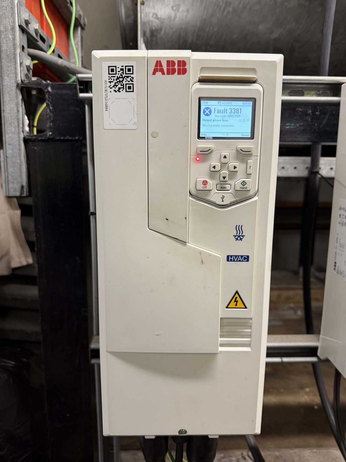
The duty extract fan drive as found: ABB ACH580, Fault 3381 latched, red fault LED lit. Everything that follows is about getting from this screen to the actual cause without guessing.
Safety. Drive fault-finding involves three-phase low voltage, stored energy in the drive's DC-bus capacitors, and rotating plant. It is work for competent persons under the Electricity at Work Regulations 1989. Isolate, lock off and prove dead with GS38-compliant equipment before opening any cover, observe the manufacturer's discharge time, and never defeat a drive's protection or reset a fault repeatedly to “see if it clears”.
Why is my AHU fan not running?
Before a single test lead comes out, separate the three things that all present as “fan not running” on a BMS graphic.
The first is a drive trip: the inverter has detected something outside its limits and has latched a fault. The keypad says so, the fault LED is lit, and the BMS fault status point — if it is wired and mapped — is active. The second is a control condition: the drive is healthy and would run, but nothing is asking it to. The Hand/Off/Auto selector is in Off, the BMS enable has dropped, the speed reference is at zero, or an interlock — fire alarm, frost stat, damper end-switch, filter differential pressure, run permissive from a pressurisation or extract-proving contact — is holding it off. The third is a mechanical or airflow problem with a running drive: the motor is turning, the keypad shows frequency and current, and there is still no air where the building needs it. That last one is a fan, damper or duct problem wearing a controls costume.
Ten minutes at the panel and the head-end sorts these out, and it decides the rest of the job. A trip is worked as below. A control condition is worked back through the unit's control strategy and the interlocks. A running-but-no-air condition is a mechanical survey. Do not start swapping drives for any of them.
What does a VSD fault code actually tell you?
Exactly what the drive measured, described in the manufacturer's words, and nothing more. The families are similar across makes even though the numbers are not.
| Fault family | What the drive measured | Where the cause usually sits |
|---|---|---|
| Supply / DC link | Incoming voltage out of range, DC bus too low or too high, supply phase missing | Upstream: supply, fuses, switchgear, loose input terminal — or a deceleration ramp too short for the load |
| Overcurrent / short circuit / earth fault | Output current spike or current to earth beyond the fast-trip limit | Motor cable, glands and terminations, winding insulation, a stalled or seized load — occasionally the drive's own output stage |
| Output phase loss / motor connection | Output current sensing cannot see three normal phases | Motor cable, terminal-box links and connections, an open winding — the case-study fault |
| Overload / stall / motor overtemperature | Current above the motor's thermal model or the load will not accelerate | Mechanical: bearings, impeller, belts, dampers shut — or wrong motor data in the drive, or a motor connected in star that should be in delta |
| Drive overtemperature | Heatsink or internal temperature limit reached | Blocked cooling fan or filters, panel ventilation, ambient in the plant room — the drive itself is rarely the fault |
| Control / communication | Reference or fieldbus lost, safe-torque-off or run-enable opened | BMS output, wiring, interlock chain, a parameter change that moved the reference source |
Two things follow. First, the code narrows the search to a region of the circuit; it does not name a component. ABB documents Fault 3381 on the ACH580 as “Output phase loss — motor circuit fault due to missing motor connection (all three phases are not connected)” and lists the remedy as “connect motor cable”; parameter 31.19 Motor phase loss is the programmable setting behind the trip, and ABB's wider motor-circuit guidance adds checking the cable phasing, the delta/star connection and the motor data in parameter group 99. On our job every one of those words was accurate and the fault was still inside the terminal box. Second, read the auxiliary code, the time stamp and the fault logger before resetting anything. Modern drives record the frequency, current and DC voltage at the moment of the trip, and whether it happened at start, at speed or on deceleration is half the diagnosis. Photograph the screen. A reset wipes the display and, repeated, wipes the evidence.
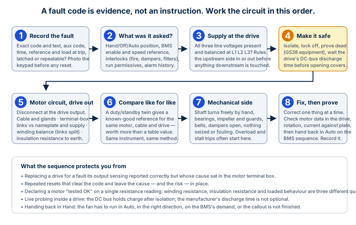
The sequence this guide follows. The order matters: it moves from the cheapest, safest observations to the tests that need the system isolated, and it keeps the drive itself as the last suspect rather than the first.
What should you check on the BMS and local controls first?
A fan on a VSD is driven by three signals from the controls: an enable (a volt-free contact or digital output telling the drive to run), a speed reference (typically 0–10 V or 4–20 mA, or a value over Modbus or BACnet), and the interlock chain wired in series with the enable. It returns at least two: a run status and a fault status, plus whatever the integration exposes over the network.
Check them in that order at the panel. Is the selector in Auto, and does the BMS think the fan should be running? Is the enable actually reaching the drive's digital input, and does the drive's own I/O status page agree? Is the reference present and sensible — a 0 V reference on a drive with a minimum speed of zero is a fan that has been told to stop, not a fault. Which interlock in the chain is open, if any, and is it open because it is doing its job? A frost stat holding a supply fan off at 3°C on a January morning is a working system. Then look back at the alarm and trend history: a drive that has tripped every morning at 06:02 for a fortnight is telling you about a start-up condition, and the BMS trends of speed and current in the minutes before each trip are free diagnostic data most sites never open.
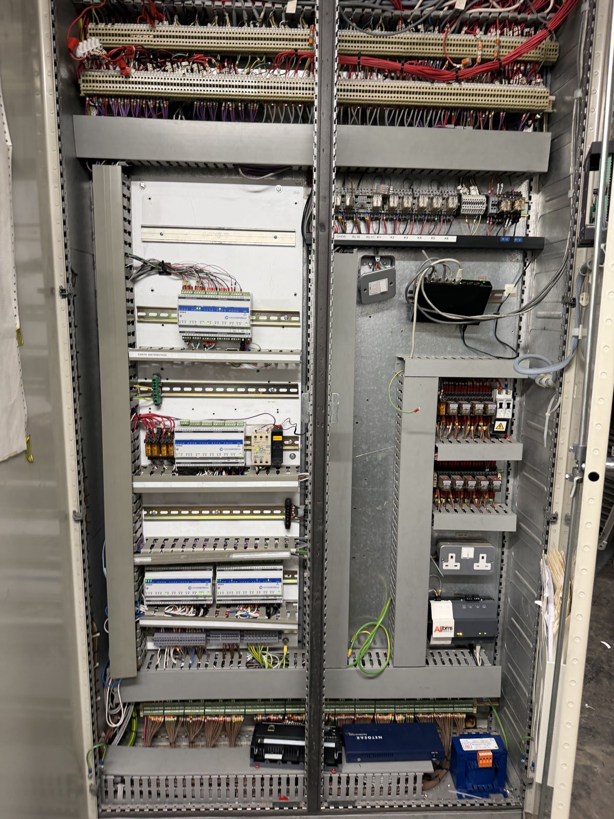
The BMS panel serving the plant on the case-study job. The enable, the speed reference and the interlock chain that decide whether a drive is even asked to run all originate here; the drive's fault is only half of the picture without them.
Get a Free BMS Survey
We'll assess your controls and provide a detailed quotation.
How do you check the supply and the drive before touching the motor?
With the drive still energised and its covers on, verify the incoming supply at the drive input terminals L1, L2, L3 using GS38-compliant probes and a meter proven on a known source: three line-to-line voltages present and balanced. On the case-study drive they read approximately 415 V on each pair, which ruled out the incoming-supply hypothesis and pointed the investigation downstream. This is the one live measurement in the sequence, it is made at purpose-designed terminals with the drive's own guarding in place, and it is still a Regulation 14 decision: if the drive's layout does not allow it to be made safely, isolate and read the supply at the upstream isolator instead.
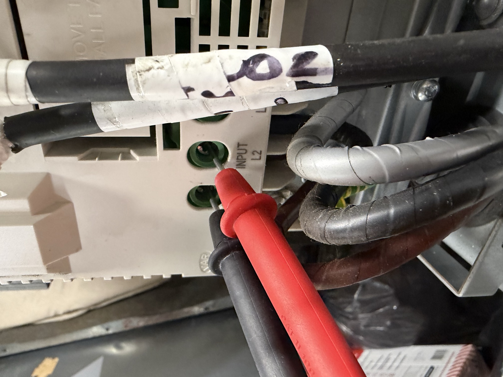
Supply check at the drive input terminals on the case-study job. All three line voltages present at around 415 V — which moved the investigation to the output side.
Then look at the drive as a piece of equipment rather than a fault source: cooling fan running, heatsink and panel vents clear, no discoloration or smell at the terminals, cable glands and screens made off properly, motor data in the drive matching the nameplate for the connection actually fitted. A drive commissioned with the star current on a motor wired in delta will trip on overload with a healthy motor, and a drive set to expect a 7.5 kW motor on a 15 kW fan will protect nothing.
How do you test the motor circuit independently of the drive?
This is where the system is isolated. Lock off the drive's supply, wait the manufacturer's DC-bus discharge time — the ACH580 label in our photographs specifies five minutes — and prove dead at the drive input and output. Disconnect the motor conductors from the drive's output terminals so that everything you measure from here is the cable and the motor alone, with no drive electronics in the circuit. Insulation testers in particular must never be applied through a connected drive.
Work the circuit in three parts. The cable: glands, screen terminations, signs of heat or moisture, and continuity core to core. The terminal box: read the connection diagram in the lid and the nameplate, then compare what is fitted with what should be. Three vertical links on an IEC board is delta; a bar across the top row is star; anything else is a finding. Our guide to three-phase motor wiring and six-terminal connections covers the layouts and nameplate readings. The windings: remove the links so each winding is independent, and measure the three resistances with the same instrument on the same range. You are looking for balance and for an open circuit, not a precision value — at fractions of an ohm, lead and contact resistance matter, and a 0.1 Ω spread on a handheld meter is method tolerance, not a fault. Then an insulation resistance test from each winding to earth with an insulation tester at the voltage the manufacturer specifies for the machine.
State the limits of these tests when you write them up. Balanced winding resistance rules out an open winding and a gross imbalance; it does not prove insulation condition. Good insulation resistance rules out a winding-to-earth breakdown; it does not find a shorted turn or a failing bearing. Neither says anything about how the motor behaves under load. In the case study the honest wording was “no evidence from this test of an open winding or obvious winding imbalance” — not “motor tested OK”. The difference matters when the fault turns out to be somewhere else.
Why is a duty/standby comparison so useful?
Because a known-good reference on the same installation beats a table value every time. Plant rooms are full of pairs: duty/standby fans, twin pump sets, two identical AHUs. If the standby motor, on the same cable type, the same drive model and the same supply, gives a consistent set of readings, then the inconsistent set on the duty motor is a finding you can act on rather than argue about.
On the case-study job the standby motor read a consistent ~0.5 Ω on all three phase pairs. The duty motor, connected as found, read about 0.2 Ω on one pair and near zero on the other two. Nobody needed a manufacturer's winding table to see that something in the duty motor's terminal box was different from its twin. The comparison also sets expectations for the drive: two identical ACH580s should show similar current at similar speed, and if one draws markedly more it is the load or the connection that has changed, not the drive.
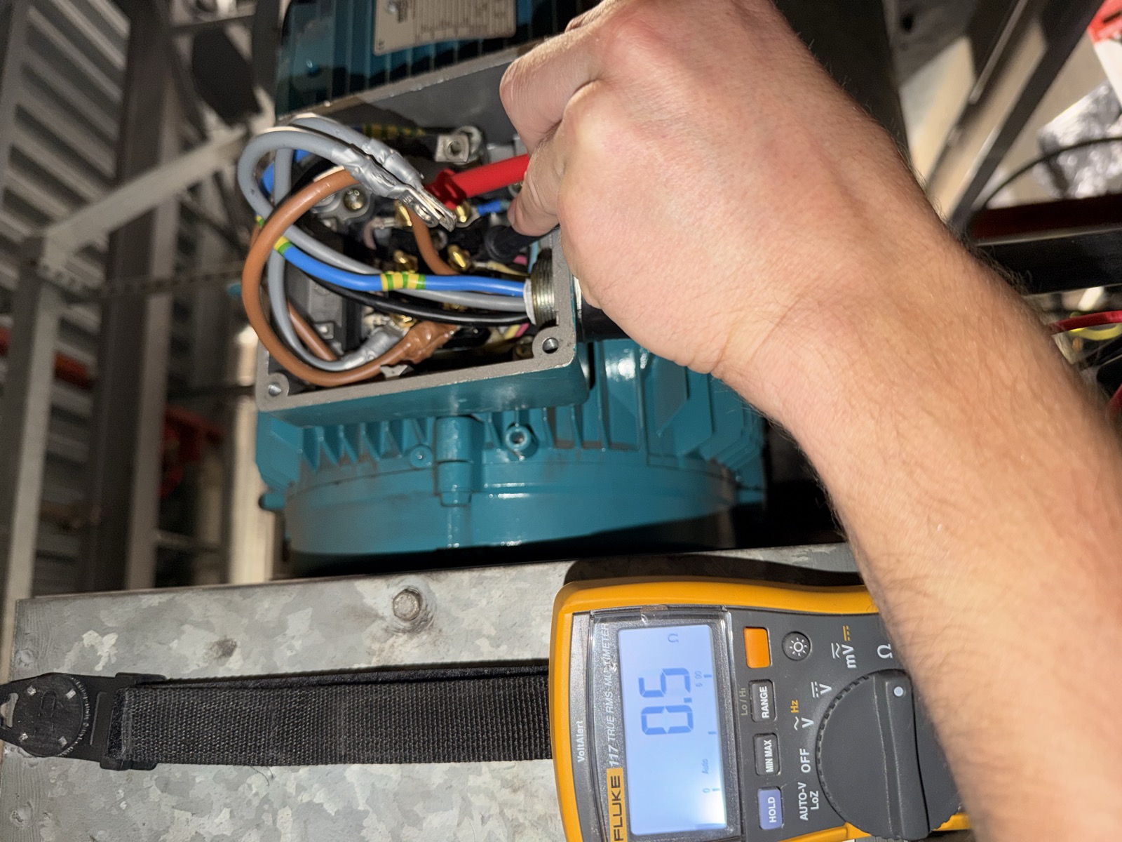
One of the individual-winding readings on the case-study motor, with the links removed: about 0.5 Ω, matching the standby motor. Diagnostic prompt, not a precision measurement — the value only means something because the other two windings and the twin motor agree with it.
What mechanical checks belong in an electrical fault-find?
More than most electrical engineers do. Overload, stall and overtemperature trips begin as mechanical problems far more often than as winding faults, and a fan that is seized, belt-bound or running against closed dampers will take a perfectly good drive down with it. With the system isolated: turn the shaft by hand and feel for roughness or stiffness in the bearings; check the impeller for damage, fouling and free rotation in the casing; check belts and pulleys where fitted; confirm the dampers the fan discharges through are open and their actuators are driving; and look at the fan's direction arrow against the impeller and the duct arrangement. A fan that has been physically re-orientated or had its impeller re-handed changes the rotation it needs, which is how the case-study job started — and the wrong response to that is in the motor terminal box, as the case study shows. The right one is in our guide on how to reverse a three-phase motor on an AHU fan.
When should you actually suspect the drive?
When the circuit around it has been eliminated. A drive that trips on overcurrent the instant it is enabled with the motor cable disconnected is telling you about its own output stage. A drive that reports a DC-link or internal fault with a balanced, healthy supply at its terminals and nothing connected to its output has an internal problem. A drive that has cooked its own cooling fan will trip on overtemperature in a plant room that is otherwise fine. These are real and they happen; the point is that they are diagnosed by exclusion, after the supply, the controls, the cable, the motor and the load have each been ruled in or out, and they are confirmed against the manufacturer's own troubleshooting table rather than a hunch. When the drive genuinely is the failed component, the replacement is a project with its own checks — our write-up of replacing an AHU extract fan inverter covers the wiring, parameters and commissioning of a swap.
Everything about the case-study fault pointed at the drive until the terminal box was opened: an “output phase loss” code, near-zero resistance readings on a connected motor, a drive that tripped within a second of every run command. The drive was retained. The motor was retained. The repair was three links and a two-phase swap on the output, and the fan went back into service at 40 Hz drawing 15.58 A on the keypad — one operating point, not a full-load claim, and recorded as such.
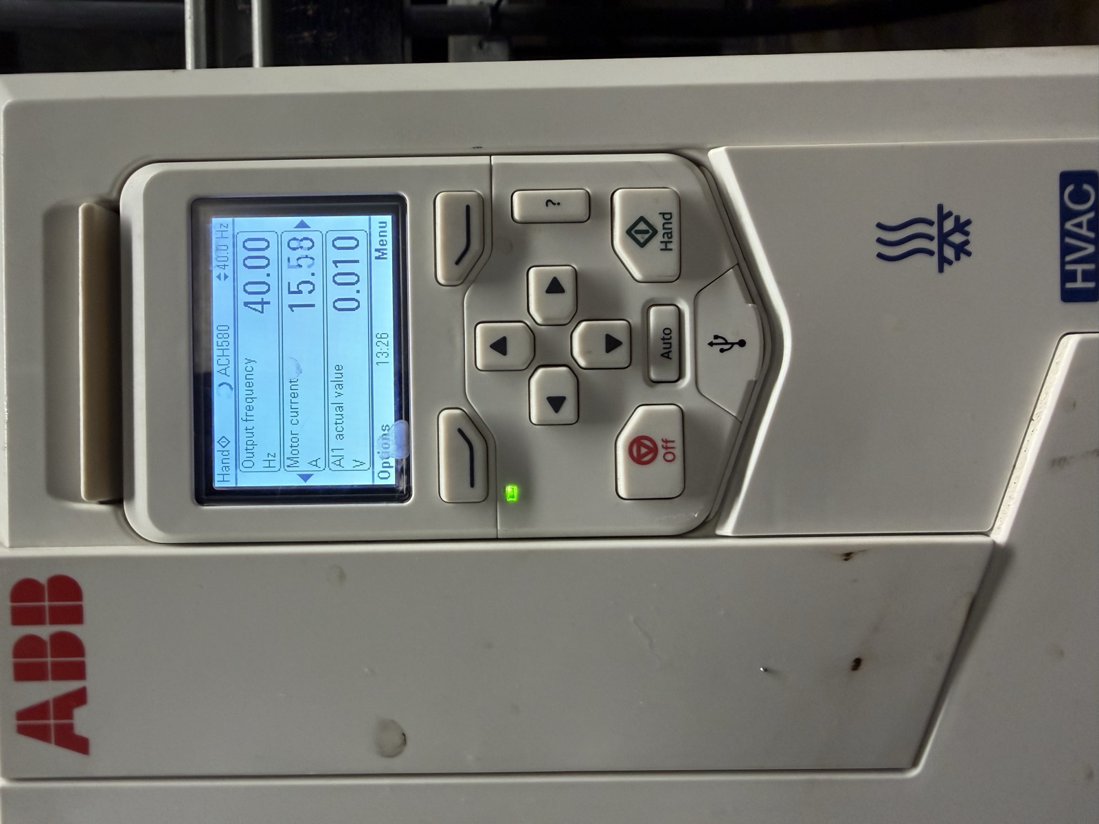
The same drive after the terminal-box repair: running in Hand at 40.00 Hz, 15.58 A, green run LED lit. No replacement drive and no replacement motor.
How do you commission the repaired fan back into service?
A repair is finished when the fan does its job under the control that normally runs it, and that is a higher bar than “the fault cleared”. Restore the connections and torque the terminals. Confirm the drive's motor data matches the nameplate for the connection fitted. Bump the motor and confirm rotation against the fan's arrow, then run it and read current against the plate; if you had to reverse it, do that at the drive output or in the drive's phase-order parameter and record which. Prove airflow, not just rotation — direction at the grille as a minimum, volume against design where the fan serves a balanced system, using the methods in BSRIA BG 49 Commissioning Air Systems. Then put the selector back to Auto, watch the BMS enable and reference bring the fan on, confirm the run and fault status points read back correctly at the head-end, and clear the alarms the fault raised. Finally, write it down: the fault as found, the readings, the cause, the repair, the parameter changes. The next engineer to open that panel is the person the record is for.
Frequently asked questions
What is the first thing to check when a VSD trips?
The fault code, its auxiliary code and the fault logger — recorded and photographed before any reset — followed by what the drive was being asked to do at the time: selector position, BMS enable, speed reference and interlocks. Then the supply at the drive input. Only after that does the motor circuit come apart.
Does an output phase loss fault mean the motor is disconnected?
It means the drive's output current sensing cannot see three normal phases. A disconnected cable is one cause; an open winding, a failed termination or an incorrect terminal-box link arrangement are others. In our case study an ABB ACH580 reported Fault 3381 with the motor fully connected but wired in an arrangement that was neither star nor delta.
Can I keep resetting a VSD fault to get the fan running?
A single reset after recording the fault is reasonable to establish whether it is latched or repeatable. Repeated resets without diagnosis are not: they destroy the evidence, stress the motor and the drive's output stage, and can turn a connection fault into a winding failure.
Does a good winding resistance or insulation resistance test prove a motor is healthy?
No. Balanced winding resistance rules out an open winding and gross imbalance; insulation resistance rules out a breakdown to earth. Neither finds a shorted turn, a bearing fault or a problem that only appears under load. Word the result as what the test excludes, not as a certificate of health.
When is it right to replace a VSD?
When the supply, controls, cable, motor and load have each been checked and the fault reproduces with the motor disconnected, or the manufacturer's troubleshooting table points to an internal component for the code and conditions you recorded. A drive should be replaced because the evidence says so, not because the code sounded like a drive problem.
Fan, drive and BMS fault-finding as one discipline
Alpha Controls treats the BMS, the electrical circuit and the mechanical plant as one system, because that is how faults present in real buildings. We fault-find and repair VSD-driven fans and pumps, the controls that run them and the BMS they report to, across London, Kent and the South East, and we set up planned maintenance so that fault loggers and BMS trends get read before the trip rather than after it. If a fan drive is tripping, a plant room has a fan that will only run in Hand, or a drive has already been replaced and the fault has come back, contact the team or request a survey. Our electrical, HVAC controls and commissioning pages set out how this work fits into the wider scope, our guide to BMS preventive maintenance in the UK covers the routine that catches these faults early, and the plant room BMS guide shows where fan and drive control sits in the wider plant room.
Evidence notes. The worked example and all photographs are from the Alpha Controls callout described in the linked case study; general guidance in this article is distinguished from what was actually done on that job, and the site and client are not identified. Measurements quoted (approximately 415 V line-to-line at the drive input; ~0.5 Ω per separated winding; 40.00 Hz and 15.58 A post-repair) are the values recorded on that job and are not presented as general reference figures.
Sources. ABB ACH580 HVAC control program firmware manual 3AXD50000027537, fault table (3381 Output phase loss) and parameter 31.19 Motor phase loss. Electricity at Work Regulations 1989 (SI 1989/635) regulations 12–14 and 16. HSE HSG85 Electricity at work: Safe working practices (3rd ed., 2013); HSE GS38 Electrical test equipment for use on low voltage electrical systems (4th ed., 2015). Brook Crompton Installation & Maintenance sheet 103-4E. BSRIA BG 49 Commissioning Air Systems.
Alpha Controls Team
Specialist BMS installation, commissioning, and maintenance across London and the South East. SafeContractor Approved, BCIA Member.