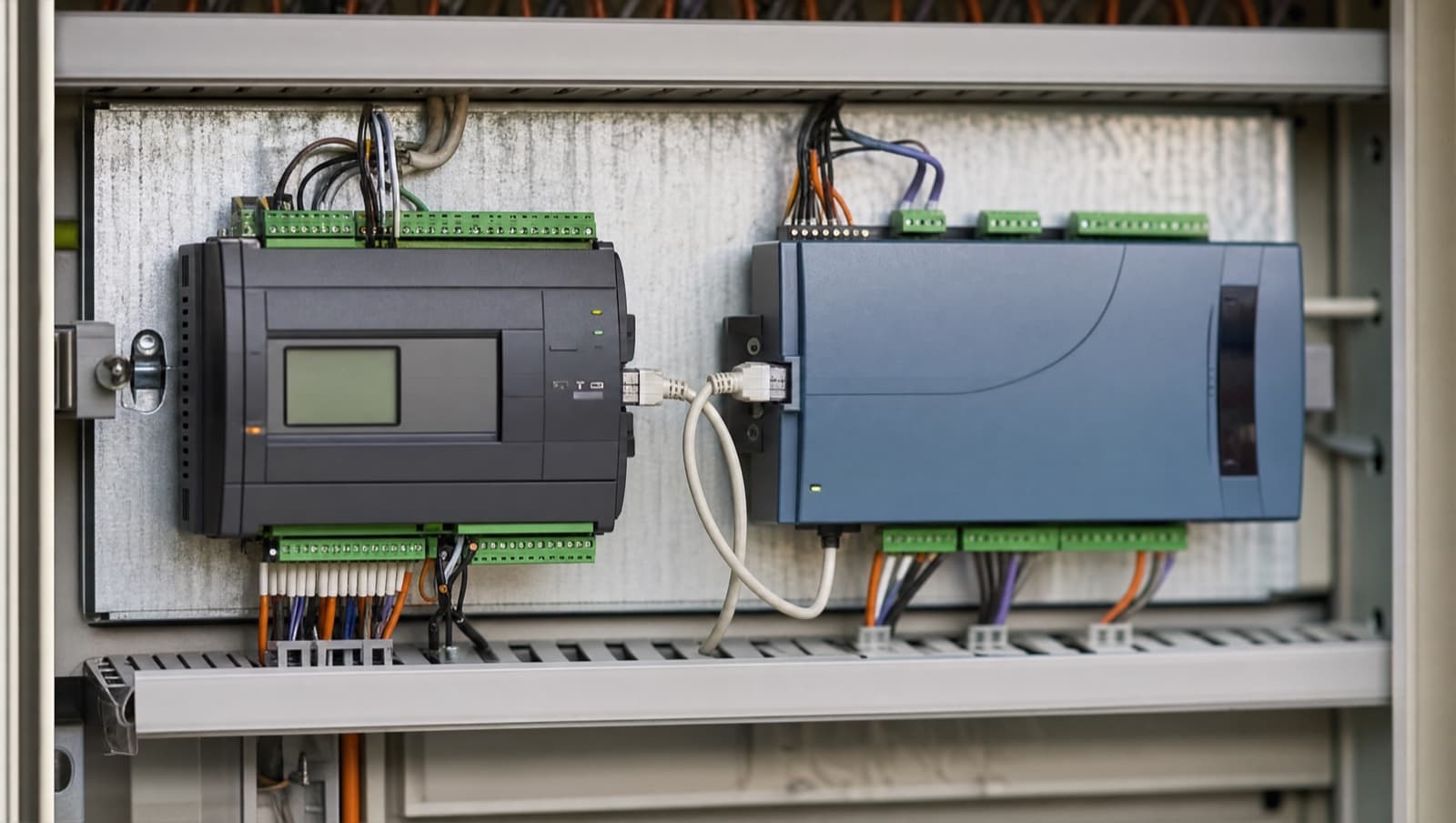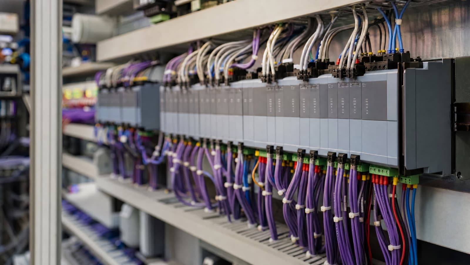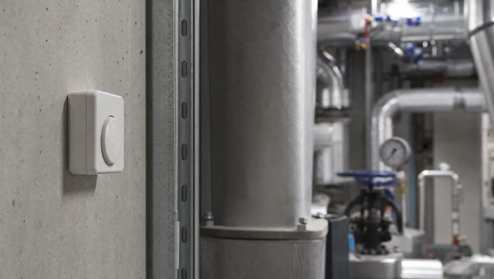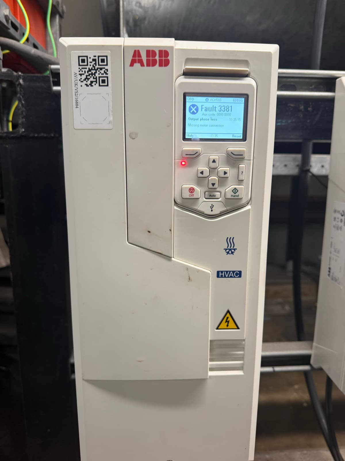

AHU controls are the sequences that decide what an air handling unit does minute to minute: when the fans run, how far the dampers open, how much heating or cooling the coils give, when heat recovery is used or bypassed, and what happens on a frost or fire signal. They are written as a control strategy, wired as a points list, and proven at commissioning.
A BMS alarms on plant that has failed, not on a sequence that is merely wrong. That is the gap these sequences live in: a unit runs for years on a strategy nobody has read since commissioning, the alarm page stays clear, and the cost turns up in the gas bill or a cold top floor.
Below: each sequence, what it decides, what has to be wired to deliver it, and the failure it produces on site. Standards are cited inline against the sequence they govern.
What are AHU controls?
An air handling unit is a box with air moving through it and things in the way of that air. The control strategy is the written logic deciding what those things do. Everything else, the controller, field devices, wiring and graphics, is how that logic gets implemented.
A supply-and-extract AHU runs seven interacting sequences. When it runs, and under what interlocks. Damper position, coordinated with the fans. Fan speed. Supply air temperature, sequencing heating and cooling so only one runs. Fresh air quantity. Whether heat recovery is used at all. And protection: frost, fire, filter and fan failure, which overrides everything above it.

Figure 1. The two air paths. Both streams enter at the top and leave at the bottom, crossing through the pack without ever mixing.
Each is a sequence, and each needs devices to sense it and outputs to drive it. The strategy is the intent; the points list and I/O schedule is the contract saying which signals exist to deliver it.
The core AHU control sequences, one at a time
Start, stop and interlocks
The unit runs to a schedule, with optimum start bringing it on early enough to hit setpoint at occupancy and no earlier. Optimum start is free, it is in every controller, and it is routinely disabled or set to a guessed pre-run time.
Underneath sit the interlocks. The supply fan does not run with the outside air damper shut. The coil valve does not sit closed while the fans run in freezing weather. The unit stops on a fire signal. Some of these belong in hardware, not software.
The damper sequence
Outside air and exhaust dampers open before the fans start and close when they stop. Order matters: a fan started against a closed damper on a sealed unit can collapse ductwork or trip on pressure, and the delay between damper end-switch and fan start is a real commissioning parameter.
A mixing unit adds a recirculation damper and the three move as a set. This is where wasted energy hides. A mixing damper stuck at full fresh air conditions the whole outside air volume all year, and nothing in the strategy alarms on it.
Fan control
Constant-volume units run their fans at fixed speed. Variable-volume units modulate against measured duct static pressure, or terminal demand.
The sequence is simple; the failure modes are not. A VSD controlling to a pressure sensor in the wrong place holds the right number and the wrong airflow. A drive that trips and restarts on its own looks healthy on the graphics and starves a floor. Diagnostic route: VSD tripping and drive fault finding.
Temperature control and coil sequencing
Supply air temperature is held to a setpoint with heating and cooling sequenced through a deadband so only one runs. The deadband is the whole sequence. Too narrow and the unit hunts, running both coils in the same hour. Too wide and the space never settles.
On many units the setpoint should not be fixed. Compensating it against outside air temperature, or resetting from the warmest or coolest zone, costs nothing but configuration time.
Fresh air and demand control
A fixed minimum fresh air position is an assumption about how many people are in the building. CO₂ sensing replaces it with a measurement, and on intermittently occupied buildings like schools, lecture theatres and meeting-room floors, the saving is substantial. The ventilation case.
The sequence is a cascade: CO₂ above setpoint opens the damper or raises fan speed; below it, back to the minimum. Demand control reduces fresh air. It does not remove the floor.
Heat recovery
In winter the recovery device is nearly always in use. In summer sometimes, recovering coolth from the extract into hot outside air, and sometimes not, which is what the bypass is for. Mid-season it may need modulating rather than switching.

Figure 2. Three recovery types, three point schedules. What the BMS has to drive or prove on each.
The control differs by device. A thermal wheel is driven and proved: a speed output and a rotation-proving input from a rim sensor, because a stopped wheel looks identical to a running one on a temperature reading. A plate heat exchanger has no moving part in the recovery device, which shifts the whole problem to the bypass damper and the frost strategy, covered in recuperator against thermal wheel. A run-around coil is a wet system: pump, three-port valve, glycol.
Protection: frost, fire, filter and fan failure
Protection is one sequence with four jobs, and it takes priority over the time schedule, the temperature loops and the fresh air demand. Frost and fire stop the unit. A dirty filter is an alarm rather than a trip. Fan proving is whichever the design makes it: wired to the BMS as monitoring it tells you a unit is running badly rather than not running at all, and wired as an interlock it stops the unit on loss of airflow.
Frost protection
Two completely different devices live in the same box and protect different things. This is the part most often got wrong.

Figure 3. Two frost devices, two jobs. Coil frost stat in the supply, protecting the coil, shutting the unit down. Pack frost protection in the exhaust, protecting recovery, changing how the unit runs.
A coil frost stat is a capillary thermostat across a water coil in the supply air, protecting the coil from splitting. It trips at around 5 °C, closes the outside air damper, stops the supply fan and drives the coil valve open.
Heat exchanger frost protection protects the recovery device, and on a plate pack it sits in the extract or exhaust, because the stream chilled below freezing is the extract, and the moisture that freezes comes out of the room air. It changes how the unit runs rather than stopping it. Full explanation: plate heat exchanger frost protection.
Both must override the time schedule. A frost sequence that only runs in occupied hours is not frost protection.
Filter and fan status monitoring
A differential pressure switch across each filter raises a dirty-filter alarm at a set pressure drop; one across each fan proves it is moving air rather than merely commanded on. The cheapest points on the unit, and the ones most often value-engineered out, which is why the BMS field device list treats them as baseline.
The fire interface
On a fire signal the unit stops and the dampers go to their fire position. Life-safety, usually hard-wired, and tested under the fire damper regime rather than BMS commissioning. The compliance side is covered in fire damper testing and BMS integration.
Why AHU control sequences matter in real buildings
A landlord sees energy and complaints: an AHU on full fresh air in January is burning gas to heat outside air, and the bill does not say why. An FM sees callouts, most of them a sequence doing exactly what it was told with bad information: a sensor reading 4 °C high, a schedule left on holiday mode, a setpoint changed and never recorded. A main contractor sees it at handover, when the unit will not pass witnessing because the frost sequence has never been tripped.
Get a Free BMS Survey
We'll assess your controls and provide a detailed quotation.
What usually goes wrong
The strategy is written for a different unit. Generic sequences get copied between projects, and a plate heat exchanger inherits a thermal wheel's rotation-proving logic.
Protection is implemented in software. A coil frost stat wired as a controller input with the fan stop written in logic is a line of code, not a safety interlock. The stat should break the fan circuit directly, with the controller monitoring the contact for alarm and logging.
Sensors are believed. A supply temperature sensor in a dead pocket downstream of a coil reads stratified air, and every decision from it is wrong by the same amount all year.
Setpoints drift and nobody records it. Six years of small adjustments by different engineers is the normal state of a ten-year-old building.
Heat recovery is left bypassed. A bypass damper opened during a commissioning problem and never closed is one of the most expensive faults we find, and it is invisible without trend data.

Figure 4. The bypass route during a defrost. Outside air round the pack through the motorised bypass damper while warm extract keeps passing through it to melt the ice.
And the sequences are never proven. Confirming the fans run and the coils get warm is not commissioning the strategy. Every protection sequence should be deliberately tripped and the response recorded.
Standards, legislation and guidance
UK Ecodesign sets the recovery floor. Regulation (EU) No 1253/2014, which still applies in Great Britain as assimilated law, requires non-residential ventilation units to achieve a minimum thermal efficiency of 73% for plate heat exchangers and thermal wheels, and 68% for a run-around coil, at the regulation's reference conditions. That is a figure for the device under test, not for the building. A strategy that bypasses recovery for long periods does not change the certified number and does change what the building gets.
CIBSE Guide H (2009), section 3.1.3.1 gives a sensor accuracy of 0.6 K across 15–25 °C for zone air temperature. Hold that against the sensors in a unit you have inherited; on older plant they are frequently well outside it. Guide H is also the reference for protection overriding time schedules.
BS EN 13053 classifies heat recovery efficiency and pressure loss in clause 6.5.2, with characteristics in Annex B, for units above 250 m³/h. Check the edition. The 2011 amendment replaced the original efficiency table with a class-based one, and the 2006, Irish 2019 and German 2020 editions are all still in circulation.
Approved Document L sets specific fan power limits, but the limit depends on the system type and the edition, and the 2013 and 2021 figures are not the same. Read the current Approved Document against the actual system type rather than carrying a number across from an old specification.
On the roof at Mulberry School for Girls
Rooftop plant at Mulberry School for Girls, east London. Five air handling units; AHU 3, 4 and 5 are plate heat exchanger supply-and-extract units with both air paths crossing inside one casing.
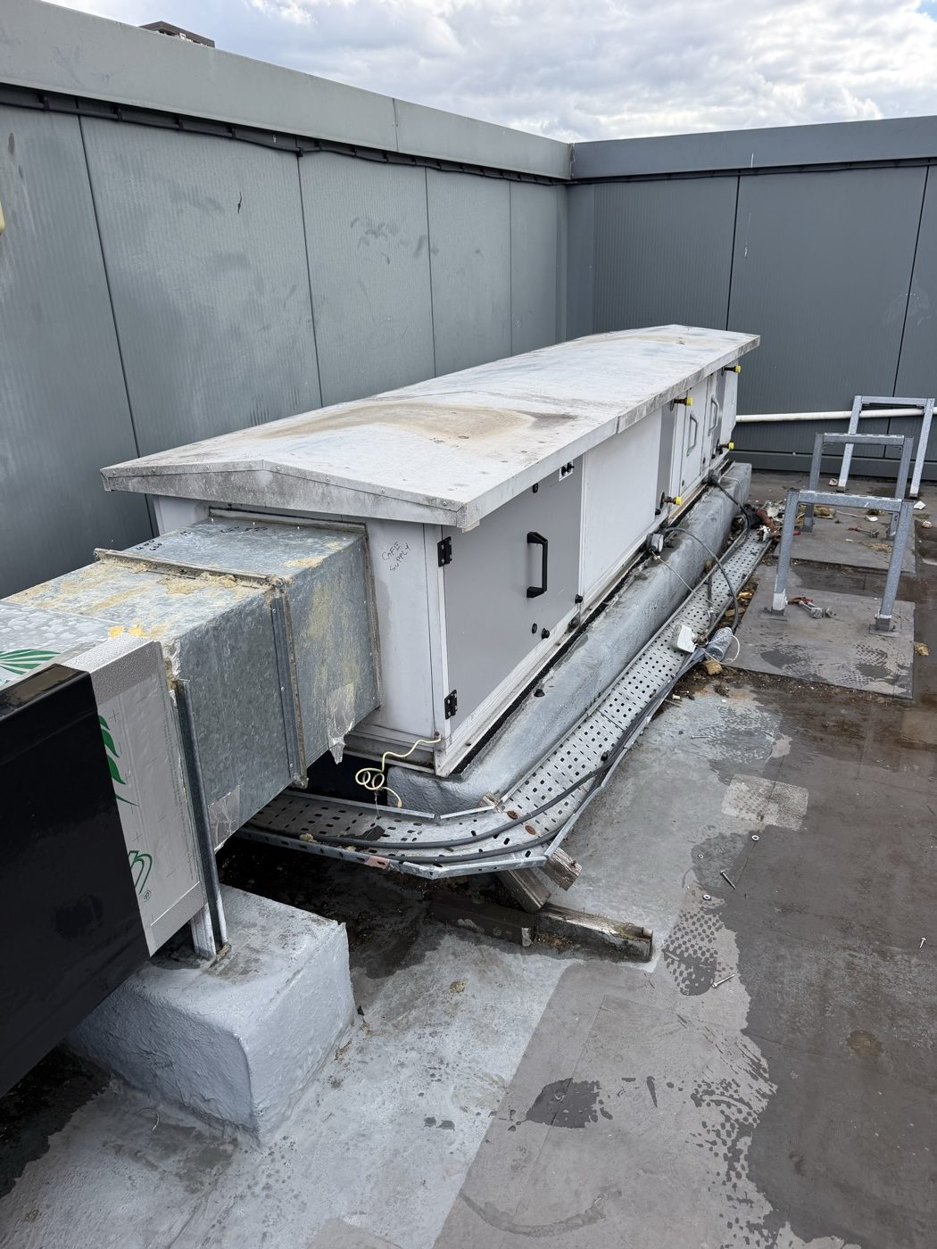
Rooftop plant at Mulberry School for Girls. Establishing what the unit is comes before the strategy is written, not after.
Scope is three device types: DP switches, rod-type duct temperature sensors and frost protection, with the original wiring retained. The frost stat is a like-for-like change in an IP-rated enclosure, which is what rooftop plant should carry.
One of our engineers queried the frost stat on the extract side. Fair question, if your experience is fan coils and conventional AHUs, where frost protection sits in the supply in front of the heating coil; on a recuperator it does not. They called another engineer, who settled it with a sketch of the two crossing air paths. Nothing got wired until it was agreed.
The containment is the other lesson. The cable tray serving AHU 1 and AHU 2 had been sat on timber supports and the timber had failed, which is what happens to wood left on a roof. It is going onto rubber rooftop feet and being refixed. Before you price a job on re-using existing cabling, look at what is holding it off the roof.
What good looks like
Establish the unit before you write the strategy: make, model, recovery device type, which dampers exist and whether they are motorised. Those four facts settle the point count, the efficiency band and the frost strategy. Getting them after the points list is written is how units end up with sequences that do not match the plant.
Write the strategy in plain English before anyone configures anything, and get the mechanical designer to agree it. Most control arguments on site are unresolved design arguments.
Hard-wire the protection. Software monitors it; it does not implement it.
Prove every sequence at commissioning, including the ones you hope never to use. Trip the frost stat. Fail the fan. Block the filter. Record what happened. Our commissioning approach witnesses the protection sequences first, not last.
Then trend it. A month of supply temperature, recovery temperature rise, damper position and fan speed tells you more than any inspection, and it is the only way to catch a bypass damper that has been open since handover.
When to act
If you are refurbishing plant, the controls decision belongs at the start with the mechanical scope, not at the end when the budget is gone. The sequence we see work is in plant room refurbishment and BMS controls.
If nobody can produce a written control strategy for a building you have inherited, that is the job to do first. You cannot optimise sequences that have never been documented, and you cannot defend an energy figure you cannot explain.
And if an AHU has been reported as working fine for years while the space it serves generates complaints, trend it for a month before anybody prices mechanical plant.
Conclusion
AHU controls decide whether the mechanical installation does anything useful. Identify the unit, write and agree the strategy, hard-wire the protection, prove every sequence, trend the result. Plant that was generating complaints usually turns out to have been capable all along.
If you have an AHU nobody can explain, or a refurbishment where the controls scope has not been thought through, talk to us or send us the details for a price.
Alpha Controls Team
Specialist BMS installation, commissioning, and maintenance across London and the South East. SafeContractor Approved, BCIA Member.