
On a plate heat exchanger AHU the frost protection watches the extract air leaving the pack, not the fresh air coming in. Ice forms on the extract side, because that is where warm, moist room air is chilled below freezing as it gives up its heat. The fresh air is being warmed, so it cannot frost.
It looks like a wiring mistake, and it gets changed
On fan coils and conventional AHUs the frost protection sits in the incoming outside air, guarding the heating coil. On a plate heat exchanger it sits in the exhaust. That is why it reads as a wiring error the first time you open a recuperator AHU.
Engineers have rewired it believing it to be an error, and lost the pack's frost protection doing it. Others leave it alone but write the strategy as though it reads outside air, so the defrost never fires at the right moment. Either way the pack ices up in January, airflow drops off, and somebody is told the unit is undersized when it is iced solid.
The device is in the right place.
Why does frost form on the extract side of a plate heat exchanger?
A plate heat exchanger moves heat between two air streams through the walls of a stack of thin plates. Cold outside air runs one set of channels, warm extract air the other. The streams never mix.
The outside air leaves warmer. The extract leaves colder, and room air carries moisture. Cool it far enough and that moisture condenses on the plate; past zero and it freezes.

Figure 1. Which stream freezes. The extract channels are the ones giving up heat; their moisture condenses on the plate surface and then freezes. The outside air channels are being warmed.
Swegon attributes frosting to exactly this: more recovery plus high indoor humidity makes the exhaust colder, which gives condensation and then frost. Systemair puts it from the surface side: in winter the exchanger surfaces drop below zero and water vapour freezes onto them.
The extract is the only stream in the box that can freeze. So the sensor sits in the air leaving to the exhaust louvre, downstream of the pack and upstream of the extract fan. Put it in the fresh air and it watches the one stream getting warmer.
Better recovery frosts sooner. A counter-flow pack pulling 85% chills the extract further than a cross-flow pack pulling 60%, so the efficient unit needs the better defrost strategy. The arrangements are compared in recuperator against thermal wheel.
Frost protection on the pack is not the coil frost stat
A recuperator AHU usually carries two frost devices doing different jobs. That is where the confusion starts.

Figure 2. Two frost devices, two jobs. Coil frost stat in the supply, protecting the coil, shutting the unit down. Pack frost protection in the exhaust, protecting recovery, changing how the unit runs.
The coil frost stat is a capillary thermostat across the face of the heating coil, in the supply air. It protects the coil from splitting. Trip at around 5 °C, outside air damper closed, supply fan stopped, every activation logged. That is the conventional sequence set out in HVAC controls integration best practices. It should break the fan circuit directly rather than run through the controller, for the reason in our BMS field device list: software is not a safety interlock.
The pack frost protection watches the exhaust air off the plate pack. It protects recovery, not the coil, and it does not shut the unit down. It opens a bypass, brings on a preheater, or drops the supply fan while the extract fan keeps running so warm room air thaws the pack.
Two streams, two responses. Schedule them as one point on a panel drawing and the commissioning engineer wires the wrong response to the wrong trip.
Get a Free BMS Survey
We'll assess your controls and provide a detailed quotation.
How the defrost is actually triggered
There is no single industry sequence. The trigger method decides what you wire, so establish it before writing a strategy.
Exhaust air temperature. A sensor in the exhaust, downstream of the pack. Systemair's temperature monitoring reduces exchanger efficiency when exhaust air falls below a preset limit.
Differential pressure across the pack. Ice narrows the plate gaps, the pressure drop climbs, and a DP sees frost before a temperature sensor does. Systemair publishes this as an approved method using a transmitter across the extract and exhaust sides. Swegon's RECOfrost works the pressure drop the other way, adjusting it when full recovery is not needed.
Two things on that. A transmitter gives a value you can trend and alarm on; a switch only changes state at a setpoint, a distinction drawn in our field device list. And a pack DP is not a filter DP: a G4 filter runs 30–50 Pa clean against 200–250 Pa loaded, per our plant room refurbishment guide. On a recuperator the bypass damper is the defrost actuator.
Temperature and humidity together. FläktGroup measures extract temperature and humidity so defrost runs only when it is needed rather than on a fixed outside-air lockout, claiming 56% efficiency held through defrost cycles well below zero.

Figure 3. The bypass route during a defrost. Outside air round the pack through the motorised bypass damper while warm extract keeps passing through it to melt the ice.
The trigger costs money. Bypass defrost stops recovery while it runs, and every minute of it is a minute the heating plant carries the full load. On a unit sized against 73%, a defrost that fires too often turns a compliant unit into an expensive one.
What the standards require
UK Ecodesign sets the hard number. Regulation (EU) No 1253/2014, which still applies in Great Britain as assimilated law, requires non-residential ventilation units to reach a minimum thermal efficiency of 73% for plate heat exchangers and thermal wheels, and 68% for a run-around coil, at the regulation's reference conditions. That is the figure the unit was sold against. Long bypass periods do not change the certified figure; they change what the building gets.
ASHRAE Guideline 36 sets out the staged sequence. Stage 1 starts when supply air drops below 4.4 °C for five minutes: hot water requests raised, outside air damper to minimum, heating coil modulating to hold at least 6 °C. It clears when supply air holds above 7 °C for five minutes. Stage 2 is a shutdown, on a freeze-stat signal, supply air below 3.3 °C for 15 minutes, or below 1 °C for 5 minutes. It stops the fans, closes the outside air damper, holds the coil at 27 °C and alarms.
Guideline 36 also settles a recurring commissioning argument. A shutdown from a low air temperature sensor stays in until an operator resets it in software, but where a frost stat with a physical reset is used there shall be no software reset switch. One reset. Two means nobody knows which cleared the trip, and the fault history is worthless.
BS EN 13053 classifies heat recovery efficiency in clause 6.5.2, with the characteristics in Annex B. Check the edition. The 2011 amendment replaced the original efficiency table with a class-based one, and the 2006, Irish 2019 and German 2020 editions are all still in circulation.
CIBSE Guide H (2009), section 3.1.3.1, gives sensor accuracy of 0.6 K across 15–25 °C for zone air temperature. Hold that against the rod sensors you inherit; on older units they are frequently well outside it. Recovery efficiency is the difference between two readings, so sensor error lands straight in the figure.
On the roof at Mulberry School for Girls
Rooftop plant at Mulberry School for Girls, east London. Five air handling units; AHU 3, 4 and 5 are plate heat exchanger supply-and-extract units, one box doing both duties with the air paths crossing in the middle.
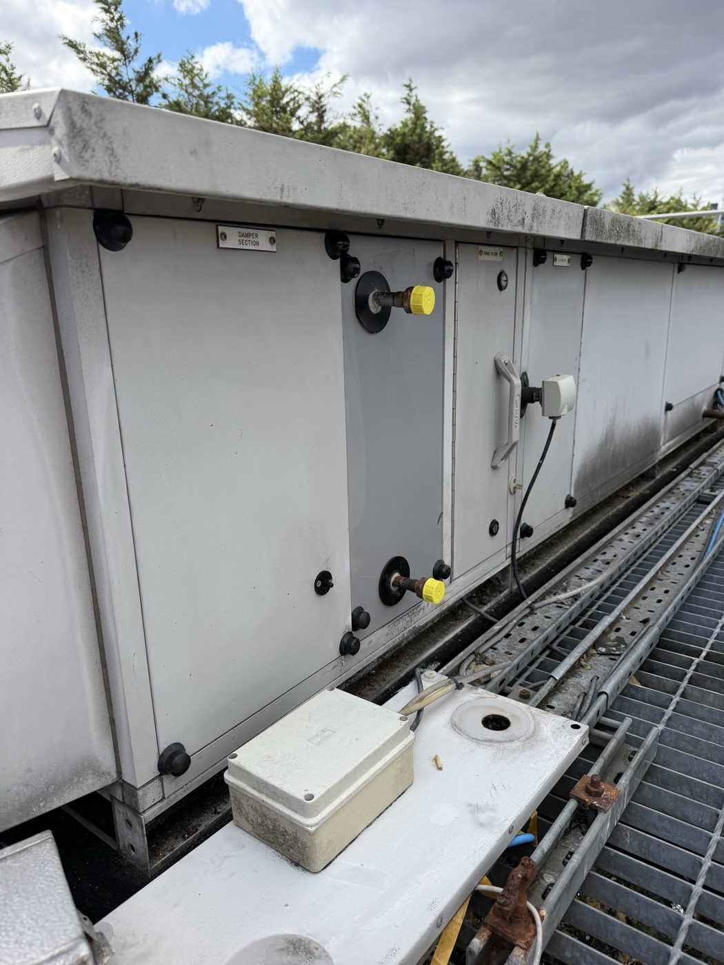
The damper section on one of the units. A field device enclosure sits on the casing and the existing junction box is on the tray below. The original wiring back to the BMS panel stays.
Scope is three device types: DP switches, rod-type duct temperature sensors and frost protection, re-using the existing wiring. On a unit of this age it is the devices that have drifted, not the copper.
One of our engineers flagged the frost stat on the extract as a wiring error. Fair call, if your experience is fan coils and conventional AHUs, where the stat sits in the supply in front of the coil. They called another engineer, who drew it: two lanes, both inlets at the top, crossing through the pack, both outlets at the bottom. Draw the crossover and the position is obvious. Nothing got wired until that was agreed.
The frost stat is a like-for-like change in an IP-rated enclosure, which is the right way round on a roof. An unrated box fills with water and the stat nuisance-trips in the wet instead of the cold.
What good looks like
Get the make and model before you price the strategy. That one fact settles the pack type, the efficiency band and the defrost method, and all three change the point count.
Schedule the two frost devices separately, with the stream each sits in written next to it, and name the response to each trip.
If the pack has a DP across it, find out whether it is a dirty-pack alarm or part of the defrost before you commission it as either.
Prove the frost trips. A frost stat that has never been tripped is an unproven device, and January is a poor time to find out. Protection must also override the time schedules rather than sit inside them. That is the point CIBSE Guide H makes, and the one we work through in trace heating and frost protection. It is part of the protection sequence, one of the seven; the rest are in our guide to AHU control sequences.
When to deal with it
Before the heating season, and before the strategy is written. This is cheap at design stage and expensive at the first cold snap: iced packs, airflow complaints, nuisance trips, and an argument about whether the unit was ever fit for the duty. If you have inherited a plate heat exchanger AHU and nobody can tell you what triggers its defrost, start there.
Alpha Controls installs and commissions AHU controls across London and the South East. Get in touch or request a quote.
Alpha Controls Team
Specialist BMS installation, commissioning, and maintenance across London and the South East. SafeContractor Approved, BCIA Member.