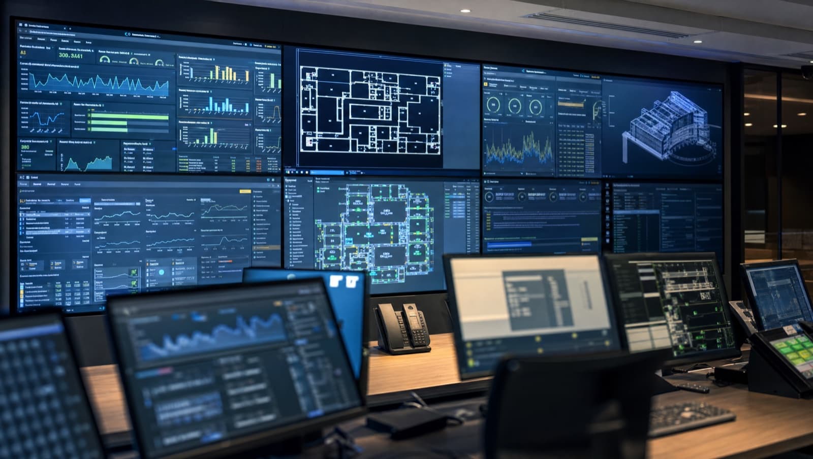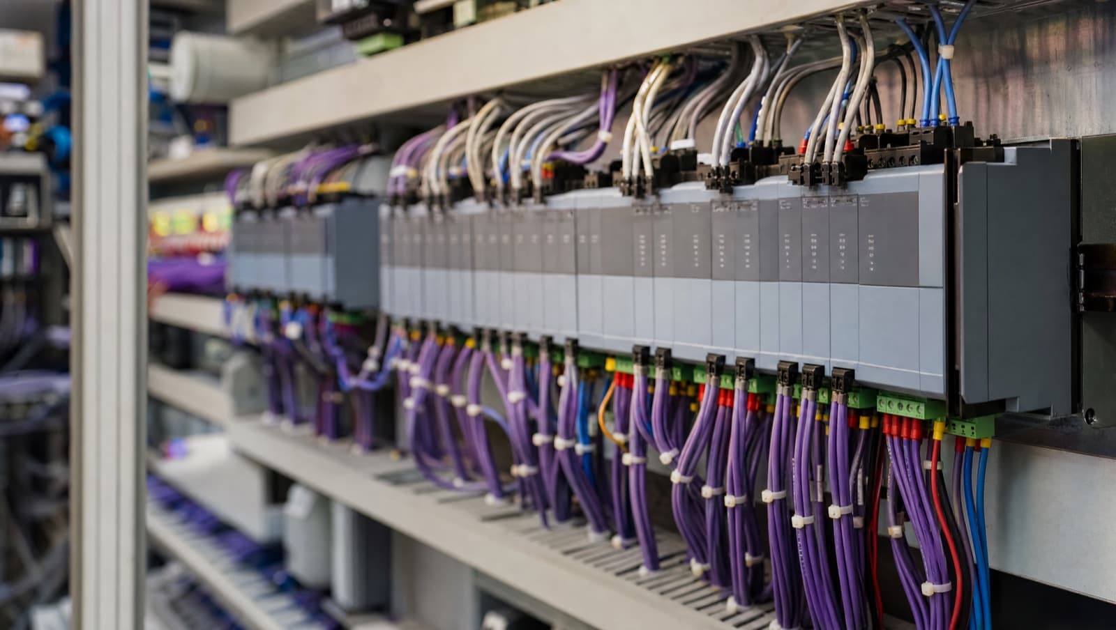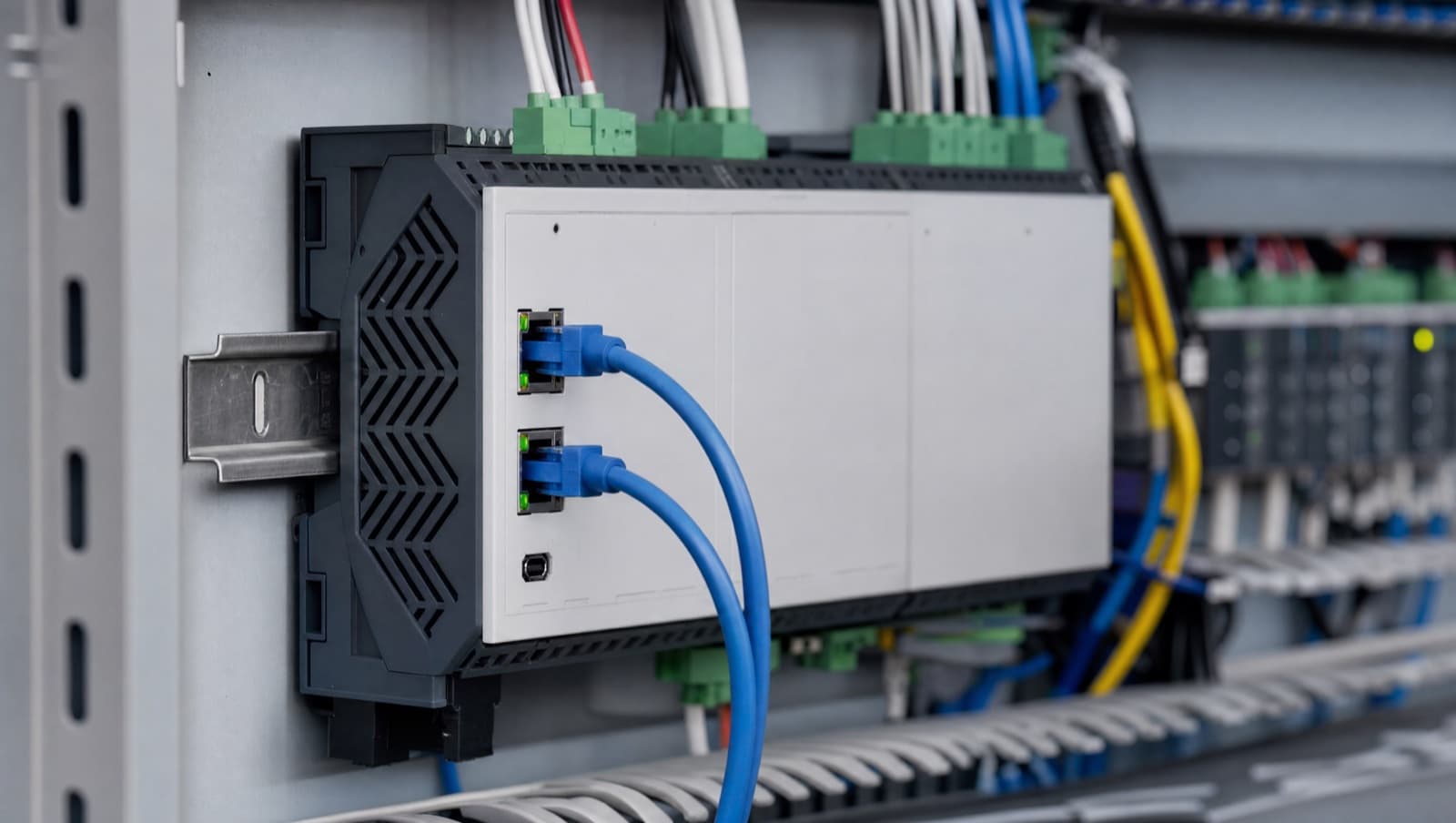

BMS field devices are the sensors, switches, actuators, valves, controllers and meters installed on plant and in occupied spaces that let a building management system measure conditions and act on them. They sit below the supervisor, at the layer where the system meets the physical building: sensors, switches, actuators, valves and meters at the bottom, and field controllers as the boundary between them and the rest of the network. Functionally they divide into equipment that measures, signals a state, moves something or counts, plus the controllers and interface hardware that tie all of it together.
Most published field-device lists are manufacturer catalogues organised by product line. That is useful once you know what you are buying and no help at all when you are specifying a system or trying to understand one you have inherited. This list is organised the way an engineer actually meets the equipment: what each device does, what signal it produces, what specification detail matters, and which ones cause the commissioning problems.
This is the field-layer companion to our guide on open protocol BMS systems. Protocols matter most above this layer: the majority of the equipment here speaks no protocol at all, the exceptions being the controllers, networked meters and some room units.
What are BMS field devices?
A field device is any component installed out in the building — in a plant room, a riser, a ceiling void, on a pipe, in a duct, on a wall — that connects back to a BMS controller. "Field" is a location and a hierarchy, not a technology: it means below the automation layer, in contact with the physical building.
The distinction that matters is between devices that generate information and devices that consume it. Sensors and switches are inputs — they tell the controller what is happening. Actuators, valves and relays are outputs — they carry out what the controller decided. Meters straddle both categories: they are inputs, but they usually arrive over a communications bus rather than a hard-wired signal, which changes how they are installed, commissioned and documented.
Nearly all of these connect by a pair of wires carrying an analogue or digital signal to a controller terminal. Only the top end — networked meters, smart actuators, some room units — speaks a protocol. This is why a building can be entirely "BACnet" and still have five hundred devices in it that have never heard of BACnet.
The complete BMS field equipment list
Grouped by what the device does rather than by manufacturer catalogue order:
| Group | Devices | Typical signal |
|---|---|---|
| Temperature sensing | Room, duct, immersion, strap-on, outside air, averaging, flue | Resistive (thermistor / Pt100 / Pt1000) |
| Humidity & air quality | Room/duct humidity, CO₂, VOC, PM2.5, differential pressure transmitters | 0–10V or 4–20mA |
| Pressure & flow | Air and water differential pressure switches, flow switches, water pressure transducers, velocity/airflow sensors | Switch = digital; transmitter = analogue |
| Status & safety switches | Frost stats, high/low limit thermostats, current sensing relays, filter differential pressure switches, level switches | Volt-free digital contact |
| Occupancy & presence | PIR, ultrasonic, dual-technology, desk and people-counting sensors | Digital contact or wireless |
| Leak detection | Point probes, sensing cable, addressable leak panels | Digital, or panel over Modbus/BACnet |
| Valves & valve actuators | 2-port and 3-port control valves, PICVs, butterfly and ball valves, thermal and motorised actuators | On/off, 3-point floating, or 0–10V modulating |
| Damper actuators | Modulating, spring-return fail-safe, fire and smoke damper actuators, VAV actuators | On/off, 3-point, 0–10V, or bus |
| Controllers & I/O | Plant/network controllers, unitary and FCU controllers, VAV controllers, remote I/O modules, room units | BACnet MS/TP, BACnet/IP, Modbus |
| Metering | Electricity meters and CTs, heat/cooling meters, water and gas meters, BTU meters | Modbus RTU, M-Bus, or pulse output |
| Interface & power | Interposing relays, contactors, current transducers, transformers, VFD/inverter interfaces, gateways | Digital, analogue, or protocol |
Sensors: what to specify and where they go wrong
Temperature sensing is the largest population by count in almost every building. Room, duct, immersion, strap-on and outside-air are the same measuring element in different housings — and the housing is what decides whether the reading is right. An immersion sensor needs a pocket and the pocket needs to sit in the flow; a strap-on that is not properly insulated reads a blend of pipe and plant room.
CIBSE Guide H (2009), section 3.1.3.1, specifies that a sensor accuracy of 0.6 K over the 15–25°C range is suitable for zone air temperature measurement. That is a checkable number to hold a supplier to, and it is worth holding them to it: every control decision the BMS makes downstream inherits the error from this device, and no amount of strategy tuning recovers a badly located sensor.
Humidity, CO₂ and air quality sensors are analogue transmitters, typically 0–10V or 4–20mA. Two things matter more than brand. First, the scaling — a 0–10V CO₂ sensor might be 0–2000 ppm or 0–5000 ppm, and getting that wrong in the controller produces readings that look plausible and are wrong by a factor of two and a half. Second, drift: CO₂ sensors need recalibration or automatic background calibration over their life, and a sensor nobody has touched in eight years is a decoration. Our guide to indoor air quality and CO₂ monitoring covers placement in detail.
Differential pressure comes in two forms that get confused in specifications. A differential pressure switch is a digital device that changes state at a setpoint — fine for filter-dirty alarms and fan proving. A differential pressure transmitter is analogue and gives you the actual value, which is what variable-speed pump and fan control needs. Specifying a switch where the sequence needs a transmitter is a rewire, not a reconfiguration.
UK suppliers worth knowing at this layer: Sontay, a UK sensor manufacturer whose range we meet regularly on site, and manufacturers including Siemens and Schneider Electric for plant-mounted instrumentation.
Get a Free BMS Survey
We'll assess your controls and provide a detailed quotation.
Switches: the devices that protect the plant
Switches are digital — a volt-free contact that is open or closed — and they carry the safety functions. Frost stats shut plant down before a coil freezes. High-limit thermostats stop a heater battery overheating. Flow switches prove there is water moving before a boiler or chiller fires. Current sensing relays confirm a motor is actually drawing current rather than simply being commanded on. On a school roof replacement in Ramsgate we replaced the differential pressure switches while the plant was being reinstated.
That last one deserves attention because it is the difference between a BMS that knows what is happening and one that only knows what it asked for. Reading a starter's auxiliary contact tells you the contactor pulled in; it tells you nothing about a snapped belt, a seized bearing or a tripped overload downstream. A current sensing relay on the motor cable proves load. On any AHU or pump where failure has consequences, that is the input worth having, and it is a small cost at installation compared with finding out from a tenant.
Safety switches are hard-wired into the control circuit as well as monitored by the BMS, and this is a point specifications routinely get wrong. A frost stat should break the fan circuit directly — not rely on the BMS reading the input and deciding to stop the fan. Software is not a safety interlock. Wire the protection, then monitor it.
Actuators and valves: where the money and the faults are
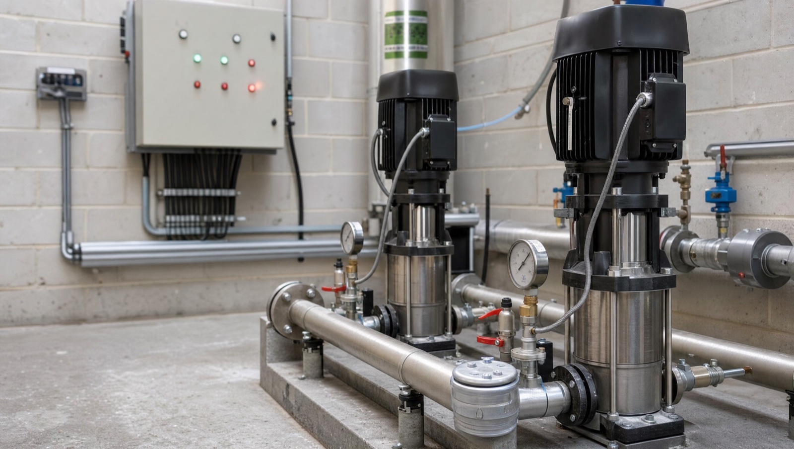
Actuators are what actually move: valve actuators driving 2-port and 3-port control valves, damper actuators on dampers and VAV boxes, and spring-return fail-safe actuators where a power loss must drive the device to a defined safe position.
Three control signal types, and mixing them up is a common commissioning fault. On/off is a single switched supply — open or shut, nothing between. 3-point floating uses two switched signals, drive-open and drive-closed, with the actuator holding position when neither is energised; the controller tracks position by run time rather than measuring it, so it needs periodic re-synchronisation to a hard stop. Modulating takes 0–10V (occasionally 4–20mA) and moves proportionally, and this is what any decent control loop wants.
The failure that consumes the most engineer time on modulating actuators is not the actuator. It is the common. A 0–10V signal is measured against a reference, and if the actuator's signal common and the controller's analogue common are not properly tied, the actuator reads a floating voltage and behaves erratically — hunting, sitting at an offset, or ignoring the signal entirely — while every device tests fine in isolation. Our step-by-step on integrating Belimo VAV actuators with Trend IQ412 controllers works through the wiring and scaling in detail.
Pressure independent control valves (PICVs) deserve a mention because they change the commissioning job rather than just the hardware. A PICV combines the control valve with a differential pressure regulator and a flow limiter, so the flow at a given position stays constant regardless of pressure fluctuations elsewhere in the system. That removes a large part of the traditional balancing exercise — but it also means the flow limit must be set correctly at installation, and a PICV set to the wrong figure is harder to diagnose than an unbalanced circuit because the system looks stable while delivering the wrong duty.
Belimo is the reference point for actuators and control valves in UK commercial work, with Danfoss, Siemens and Schneider all holding significant valve ranges. On dampers, the actuator and the damper frequently come from the same manufacturer as an assembly, which is usually the right way to buy them.
What are field controllers in a BMS?
A field controller is the device that reads the inputs, runs the control strategy and drives the outputs for a defined area of plant. It sits above the sensors and actuators and below the supervisor, and it is the first device in the chain that speaks a protocol.
They come in three broad shapes. Plant or network controllers — a Trend IQ4NC, a Distech ECLYPSE — handle large plant such as AHUs, boiler and chiller sets, and often route between network segments. Unitary controllers are smaller fixed-application devices for fan coil units, VAV boxes or heat pumps, typically with a fixed I/O count and a configurable rather than freely programmable strategy. Remote I/O modules add input and output channels to a controller that has run out, without adding another processor.
Channel counts and channel types are what catch people out at design stage. A controller advertising twelve inputs may support only four of the resistive type your temperature sensors need, or may share channels between functions so that using one disables another. Getting that wrong is discovered at second fix, when the panel is built. Our guide to inputs and outputs on Trend IQ4NC and IQ ECO 412 controllers covers exactly this.
Where field controllers sit on the network is a wiring question, not a software one. BACnet MS/TP runs over RS-485 as a straight bus — screened twisted pair, characteristic impedance 100–130Ω — with 120Ω termination at each of the two physical ends of the segment, and only there. A Trend IQ4NC provides an integral 120Ω terminator switched in at one end, with a 120Ω resistor across the MS/TP terminals at the far end (Trend IQ4NC data sheet TA201285). Note that this applies to the MS/TP fieldbus specifically: a traditional Trend IQ site Lan runs as a current loop and uses no 120Ω termination at all, so looking for one on an older Lan is looking for something that was never fitted.
Meters: the field devices that have to be right
Meters are field devices with a different burden of proof, because their output may end up on a tenant's bill or in a statutory energy report. Electricity meters with current transformers, heat and cooling meters, water meters and gas meters all fall here.
Three connection types. Modbus RTU over RS-485 is the most common on electricity meters — open, universal, and completely dependent on having the register map, because a Modbus device hands back a number and nothing that explains it. M-Bus is purpose-built for metering and defined in EN 13757-2 (physical and link layer) and EN 13757-3 (application layer), with wireless M-Bus in EN 13757-4; it is designed for many meters on a long two-wire bus. Pulse outputs are the simplest — a contact closure per unit consumed — and the least informative, giving you consumption and nothing else.
For heat metering, EN 1434 sets the requirements for heat meters including accuracy classes, and it is the standard that decides whether your data is billable or merely indicative. If the meter output is going anywhere near a tenant recharge or a heat network obligation, it needs to be an appropriate, conformity-assessed instrument — retro-fitting that after someone queries an invoice is expensive. Our guide to sub-metering in commercial buildings covers the design side.
The recurring practical failure with meters is not the meter. It is the CT — a current transformer fitted on the wrong phase, fitted backwards, or specified for the wrong ratio. A reversed CT gives a clean, plausible, negative reading; a wrong ratio gives a clean, plausible reading that is wrong by a fixed multiple and can survive years without being questioned. Verify meter readings against a known load at commissioning rather than accepting that the value is populated.
Is BMS a type of SCADA?
No, though the architectures rhyme and the confusion is understandable. Both are supervisory control systems with a field layer of sensors and actuators, controllers above it and a supervisory interface on top.
The differences are in purpose and consequence. SCADA is an industrial-process technology — water treatment, power distribution, manufacturing lines — usually built on PLCs, with control loops where a failure can be immediately hazardous or halt production, and it is normally engineered to industrial standards accordingly. A BMS controls building services: heating, cooling, ventilation, lighting, hot water. It runs to standards written for building automation, principally the BS EN ISO 16484 series, and it prioritises comfort, energy performance and compliance rather than process throughput.
In practice you meet both in the same building, particularly on larger campuses and data centres, and the interesting engineering is at the boundary between them.
Standards that govern the field layer
BS EN ISO 16484-5 is the data communication protocol standard for building automation — the international adoption of BACnet, and what a specification should cite for anything networked at this layer, in preference to a brand name. BS EN ISO 16484-2 covers hardware requirements for building automation and control systems, which is the part that speaks to field equipment rather than to protocols.
BS 7671 (the IET Wiring Regulations, published by the IET) governs the electrical installation of everything in this list — containment, segregation of band I signal cabling from band II power cabling, earthing and testing. Field-device wiring that shares containment with power cabling is a classic cause of noise on analogue inputs and a classic cause of a failed inspection, and the two problems usually arrive together.
CIBSE Guide H remains the reference for building control systems generally, including the sensor accuracy figure above, and BSRIA publishes the commissioning guidance that decides whether the installed devices actually get proved rather than just energised.
What good looks like: the field device schedule
Every well-run BMS project has one document doing the heavy lifting, and it is not the specification. It is the field device schedule — a row per device listing type, manufacturer and model, location, the controller and terminal it lands on, signal type, range and scaling, and the point name it appears under on the graphics.
Build it at design stage and it prices the job, tells the panel builder what to wire, tells the commissioning engineer what to prove, and becomes the asset register the FM team inherits. Skip it and every one of those four jobs gets done from memory, which is where the wrong CT ratio and the unscaled CO₂ sensor come from. It is also the document that makes a system genuinely maintainable by somebody other than the original installer — the field-layer equivalent of the handover items in our guide to BMS vendor lock-in.
Commission it device by device against that schedule. Override each output and confirm the right thing moves. Compare each input against a calibrated instrument at the device, not at the graphics page. A point that reads a plausible number is not a proven point, and the gap between those two is where inherited BMS problems live.
When to survey your field devices
If you have inherited a building with no device schedule, that survey is the first thing worth buying — before any strategy work, because tuning a control loop on top of an unproven sensor is guesswork with an invoice attached. If you are planning a controller upgrade, the field layer usually survives it: sensors, valves and actuators frequently have life left when the controllers do not, and knowing which ones do is the difference between a proportionate retrofit and an unnecessary strip-out. And if energy figures have never reconciled with the utility bills, start at the CTs and the meter register maps rather than at the reporting software.
Alpha Controls surveys, installs, replaces and commissions BMS field equipment across London, Kent and the South East — on Trend, Distech, Siemens, Schneider and mixed inherited estates. If you need a field device schedule building from an existing system, or a survey before an upgrade, get in touch or request a quote.
Alpha Controls Team
Specialist BMS installation, commissioning, and maintenance across London and the South East. SafeContractor Approved, BCIA Member.