
A recuperator AHU recovers heat through a static plate heat exchanger. Supply and extract run in one box, through separate channels in a stack of plates, and never mix. A thermal wheel does the same job with a rotating matrix, which recovers moisture as well as heat but allows a small amount of air to carry over between the streams.
You cannot price the controls until you know which type it is
The recovery type decides the point count. A plate recuperator and a thermal wheel of the same duty need different devices, different proving and different responses to a frost trip. Price one as the other and the job is wrong before the first cable goes in, usually short, because a wheel carries a rotation-proving input and a drive output that a plate pack does not. The three types also sit in different efficiency bands, which matters to anyone signing off a Part L submission.
What is a recuperator AHU?
A recuperator is the heat exchanger itself: a stack of thin plates forming alternating channels, the two air streams passing through adjacent channels, heat crossing the plate wall. The complete box around that pack, with its filters, fans, coil, dampers and controls, is the air handling unit.

Figure 1. The two air paths. Both streams enter at the top and leave at the bottom, crossing through the pack without ever mixing.
A recuperator AHU is a supply unit and an extract unit in one box. Outside air enters one end, extract air from the rooms the other, both cross the pack, and they leave as supply air to the rooms and exhaust air to atmosphere at opposite ends. Seeing "supply" and "extract" on the same unit is the giveaway, and it is why the frost protection position looks wrong until the airflow is drawn out. That has its own article.
A standard plate pack transfers sensible heat only. Enthalpy plates use a moisture-permeable membrane so some humidity transfers too, but they are the exception in UK commercial work.
Cross-flow or counter-flow? It changes the number you quote
In a cross-flow pack the two streams run perpendicular to each other through the plates. Sentera describes this as the most common type, and the practical reason is duct sealing: cross-flow is simpler to seal into a compact casing.
In a counter-flow pack the streams run in opposite directions along the plates, holding a temperature difference across the whole length rather than only where they cross. More contact, more recovery, deeper unit.
Published figures disagree, so check before you quote one. An experimental comparison from Gazi University puts cross-flow at roughly 50–75% and counter-flow at 75–95%. A separate review narrows the gap to around 10 percentage points, capped in the mid-80s. Nuaire gives plate exchangers at 80–90%, the same band as its wheels.
Arrangement, plate geometry, face velocity and test conditions all move the number. Put the manufacturer's certified performance for that unit in the document and nothing else, because what sits underneath the range is a legal minimum.
Get a Free BMS Survey
We'll assess your controls and provide a detailed quotation.
Recuperator versus thermal wheel
Heat recovery sits on the AHU because the AHU is the only plant item handling both air streams, which is the point made in AHUs vs FCUs.
A thermal wheel is a rotating matrix turning slowly between the two streams, taking heat from the extract on one half-turn and giving it to the supply on the next. Strictly it is a regenerator, a storage mass, where a plate pack is a recuperator with a fixed barrier. HVAC usage is loose and some manufacturers group both under "recuperator", so watch for it in a specification.

Figure 2. Three recovery types, three point schedules. What the BMS has to drive or prove on each.
| Plate recuperator | Thermal wheel | Run-around coil | |
|---|---|---|---|
| How heat crosses | Fixed plates, streams never meet | Rotating matrix carries heat between streams | Water or glycol circuit between two separate coils |
| Moisture recovery | Sensible only, unless enthalpy plates | Yes, condensation, enthalpy or sorption types | No |
| Carry-over between streams | None by design | Small amount, reduced by a purge sector | None, the streams never share a casing |
| Moving parts in the recovery device | None | Wheel drive and bearings | Circulating pump |
| Streams must be adjacent | Yes, one casing | Yes, one casing | No. Supply and extract can be in different plant rooms |
| Typical weak point | Frosting on the extract side | Wheel stalling, belt or drive failure, seal wear | Lowest efficiency of the three |
| UK Ecodesign minimum | 73% | 73% | 68% |
Sentera splits rotary types by what they recover: condensation wheels in cold seasons only, enthalpy types in cold and transitional seasons, sorption types all year.
From a refurbishment point of view the three come down to what the BMS drives: wheel speed, bypass damper, circulation pump. Our plant room refurbishment guide sets that out alongside the rest of the plant.
Neither is better in the abstract. A wheel suits a building needing moisture transfer, or a compact unit for the duty. A plate pack suits streams that must stay strictly apart, or a tight void. A run-around coil suits dirty exhaust, which is why it turns up on kitchen extract, and it is the only one that works when supply and extract plant are nowhere near each other.
What the controls contractor actually has to wire
A plate recuperator has no moving part in the recovery device, so nothing to prove rotating. The point list: a DP switch across each filter, a DP across each fan to prove it is moving air, supply and extract air temperature sensors, a sensor in the air leaving the pack, frost protection in the exhaust, and a bypass damper with an actuator if one is fitted. Optionally a DP across the pack, which sees ice narrowing the plate gaps before a temperature sensor does.
A thermal wheel adds two points. A drive output, because wheel speed is modulated to control recovery. And rotation proving. A stalled wheel is the classic heat recovery failure: the unit runs, the fans prove, the filters are clean, nothing alarms, and recovery has gone to zero. Only a proximity sensor on the rim, wired back as a proving input, catches it. Leave it out of the schedule and nothing tells you the recovery has gone until the gas bill arrives.
A run-around coil is not an air-side problem at all. It is a wet system: a circulating pump to start and prove, a three-port valve and actuator, flow and return sensors, and frost protection on the glycol. Price it as an air-side package and you have missed most of the points.
Three types, three point schedules. That is why you get the make and model before quoting. It all lands as inputs and outputs on a document somebody has to read: the points list. Heat recovery is one of the seven; the rest are in our guide to AHU control sequences.
What the standards require
UK Ecodesign is the binding one. Regulation (EU) No 1253/2014, which still applies in Great Britain as assimilated law, sets a minimum thermal efficiency of 73% for plate heat exchangers and thermal wheels, and 68% for a run-around heat recovery system for non-residential ventilation units at the regulation's reference conditions.
Hold that against the cross-flow figures above. A plain cross-flow pack at the lower end of its range does not obviously clear 73%, which is part of why counter-flow and cross-counter-flow have become normal in the non-residential market. Check the certified performance for the actual unit.
BS EN 13053 classifies heat recovery efficiency and pressure loss in clause 6.5.2, with characteristics in Annex B, for units above 250 m³/h. Check the edition. The 2011 amendment replaced the original efficiency table with a class-based one, and the 2006, Irish 2019 and German 2020 editions are all still in circulation.
BS EN 1886:2007 covers the casing, not the recovery device: mechanical performance, leakage, thermal transmittance and bridging classes. Quote it for casing performance, never for recovery efficiency. That distinction gets muddled in specifications.
CIBSE Guide H (2009), section 3.1.3.1, gives sensor accuracy of 0.6 K across 15–25 °C for zone air temperature. Measured recovery efficiency is the difference between two readings, so sensor error lands straight in the figure.
On the roof at Mulberry School for Girls
Rooftop plant at Mulberry School for Girls, east London. Five air handling units, three of them plate recuperators with supply and extract in one casing.
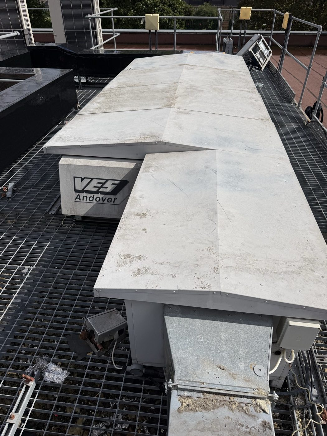
One of the rooftop units. Supply and extract in one casing, which is what makes the frost protection position look wrong until the air paths are drawn out.
Scope is three device types: DP switches, duct temperature sensors and frost protection, with the original wiring retained. Devices drift and fail; cable in good containment does not.
Establishing what the units were took longer than fitting the devices. One of our engineers queried the frost protection reading the extract, since it does not match the pattern on fan coils or conventional AHUs. They called another engineer, who settled it with a sketch of the two crossing air paths.
The containment is the other lesson. The cable tray around AHU 1 and AHU 2 had been sat on timber supports and the timber had gone, which is what happens to wood left on a roof. It is going onto rubber rooftop feet and being refixed. Look at what is holding the cable off the roof before you price a job on re-using it.
What good looks like
Identify the unit before you price it: make, model, pack arrangement, and whether a bypass damper is fitted and motorised. Those four facts settle the point count, the efficiency band and the frost strategy.
Put rotation proving in the schedule on every thermal wheel, without exception. One input, and the only thing between a stalled wheel and a winter of heating outside air from scratch.
Quote the manufacturer's certified efficiency at stated conditions, never a type-level figure off a web page.
Keep the two frost devices distinct on the drawing. They do different jobs in different air streams and need different responses.
And treat it as a maintenance decision, not only a design one. A bypassed recovery wheel is common enough on buildings over five years old that we wrote about it in why sealed buildings need AHUs. A device nobody can prove is working gets bypassed and stays bypassed.
When to act
At survey, before the price. A heat recovery AHU surveyed properly takes an extra half hour and settles the point schedule. Surveyed as "an AHU" it produces a quotation wrong in both directions: missing points on a wheel, invented points on a plate pack. And if you are specifying a replacement, the choice between plate and wheel is made on moisture, carry-over and space, not a headline efficiency number.
Alpha Controls installs, replaces and commissions AHU controls across London and the South East. Get in touch or request a quote.
Alpha Controls Team
Specialist BMS installation, commissioning, and maintenance across London and the South East. SafeContractor Approved, BCIA Member.