
The short answer: a VAV installation on a refurbished office floor is a two-trade job. The mechanical contractor replaces the ductwork and hangs the VAV terminal units; the controls contractor cables each VAV and CO₂ sensor back to the BMS panel, terminates the factory-fitted controller (24 V supply, 0 V, control signal Y, feedback U), isolates the unused bus cores and proves every unit responds before handover.
That's the whole job in one paragraph. The detail is where floors either work on day one or turn into months of hot-and-cold complaints, because a VAV that looks finished can still be running on the wrong signal range, the wrong mode, or a feedback wire the BMS is reading as something it isn't.
This is a write-up of a recent one: level three of a multi-storey commercial office, where the old galvanised extract and return ductwork came out, new ductwork went in with four TROX VAV terminal units, and we wired the lot back to a Trend controller two floors up.
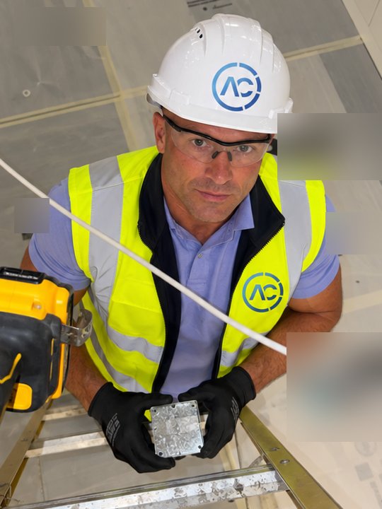
What was the VAV installation job?
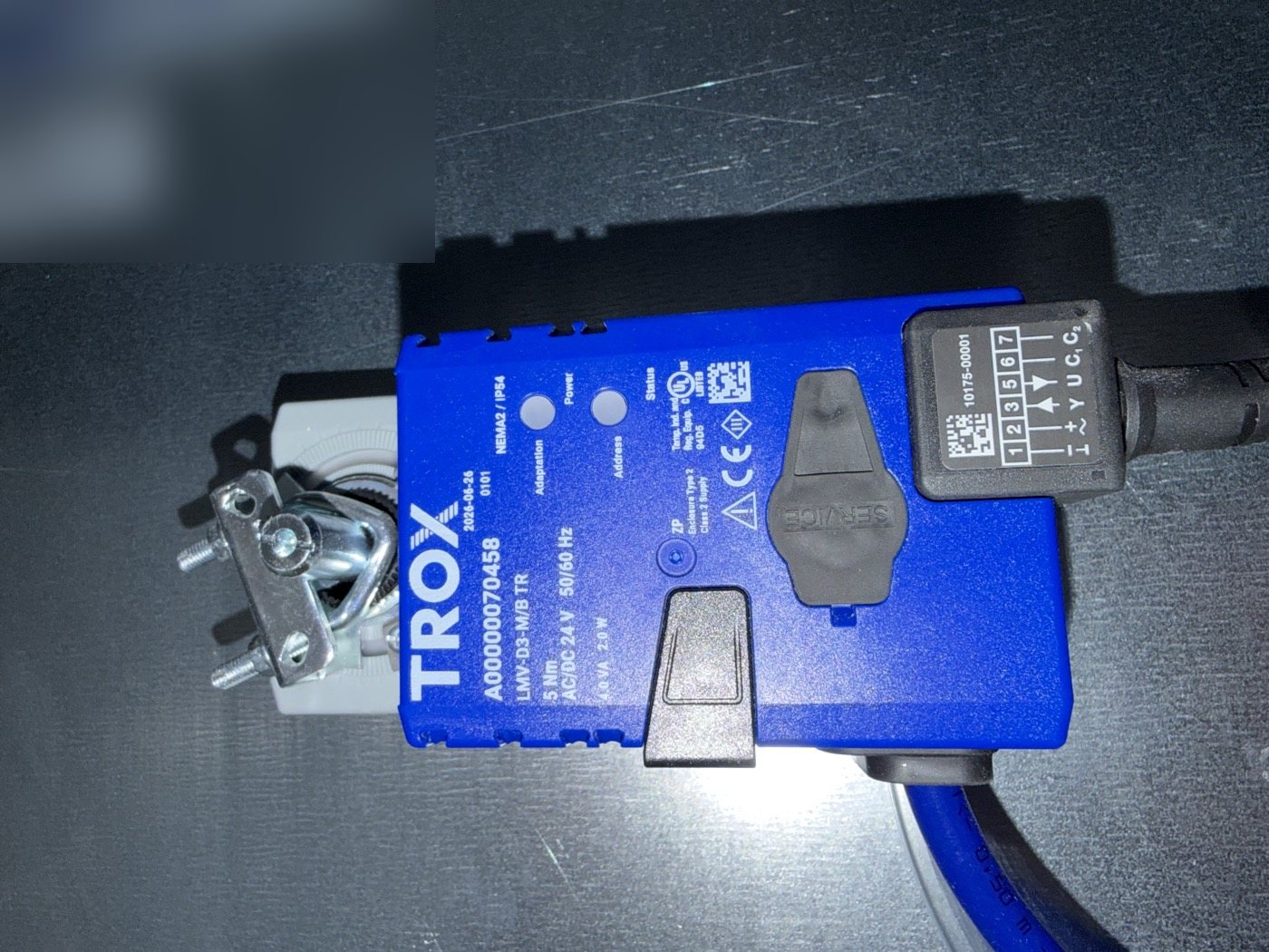
The mechanical contractor stripped out the existing tin extract and return ductwork across the main floor on level three and replaced it with new ductwork carrying four VAVs. The units are TROX TA-Silenzio — a rectangular VAV terminal unit with an integral sound attenuator, which TROX designs specifically for extract air in buildings with demanding acoustic requirements. Each one arrived with its control components factory-mounted, piped and wired: an averaging differential pressure sensor across the airway, a damper blade, and a TROX-badged compact controller (type LMV-D3-M/B TR, 5 Nm, AC/DC 24 V) sitting on the damper shaft with its blue and clear pressure tubes running to the sensor.
Once the mechanical side was hung, our scope was the controls. We ran cable from the Trend panel in the level five riser down to level three, through the ceiling void on the cable management, cable-tied along the route and supported with metal ties at intervals. At every VAV position we drilled a galvanised adaptable box, brought the VAV controller's flex into it through a gland, and ran a dedicated Belden back to the panel on level five. We terminated both ends — the adaptable box at the VAV, and the controller inputs and outputs in the panel.
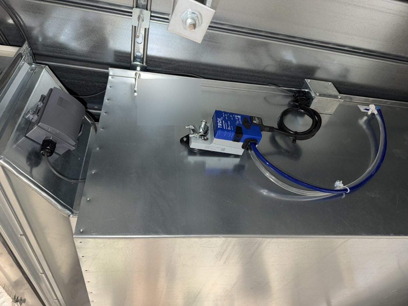
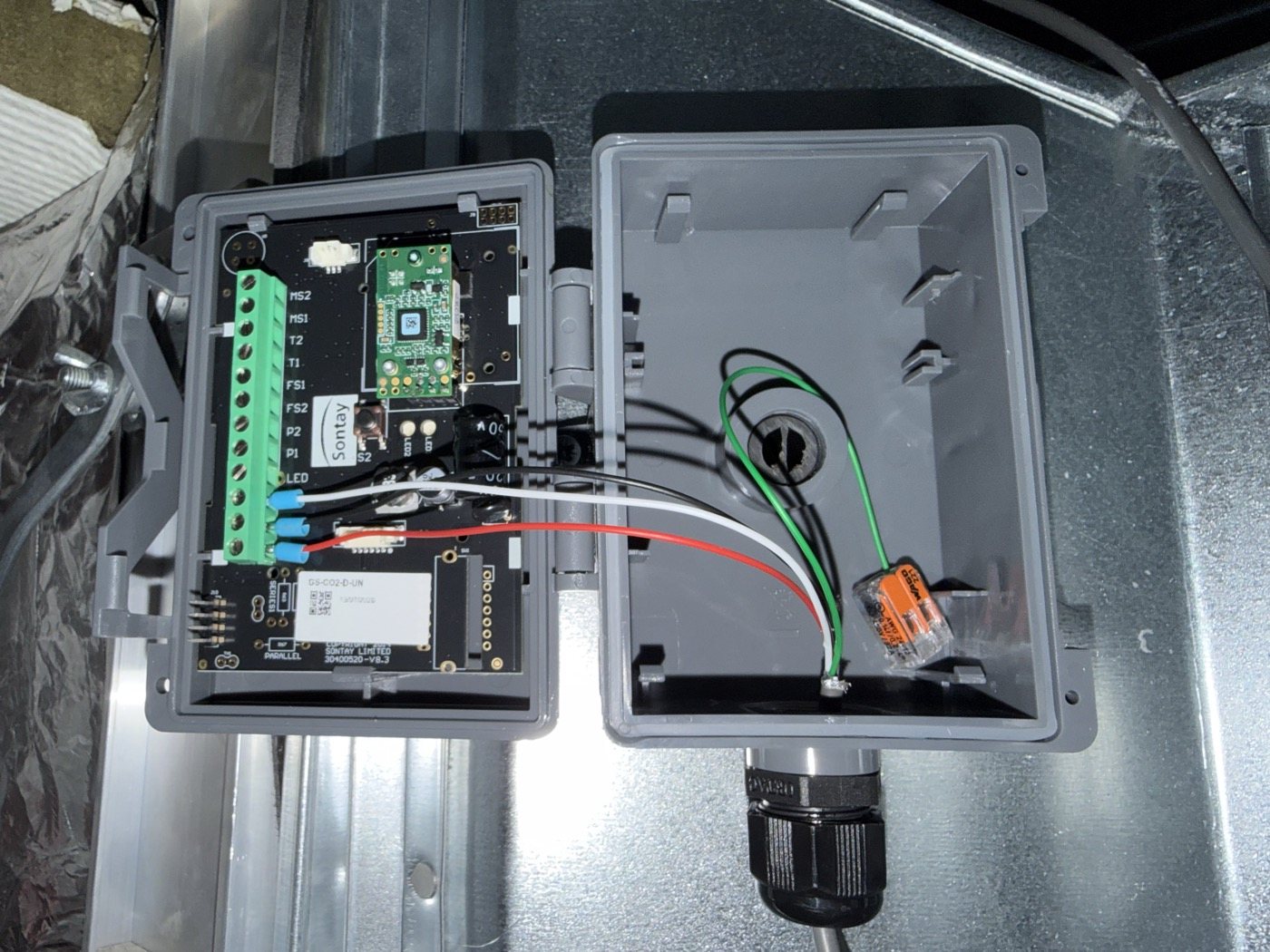
On the extract ducts we also installed Sontay GS-CO2-D duct CO₂ sensors, again on Belden back to the panel, so the BMS can see what the air leaving the floor is actually carrying.
How do you wire a TROX VAV controller to a Trend BMS?
The TROX compact controller is built on the Belimo VAV-Compact platform, and its flex has six cores, numbered on the connector. For conventional analogue control from a Trend controller you need four of them, and the Belden cores map across like this:
| Belden core | Controller wire | Terminal | Function |
|---|---|---|---|
| Black | Black | 1 (⊥) | 24 V common / 0 V |
| Red | Red | 2 (~ +) | 24 V AC/DC supply |
| White | White | 3 (Y) | Control input (setpoint) |
| Green | Orange | 5 (U) | Feedback output |
Three cores will give you power and control. The fourth brings feedback back to the BMS, and on a VAV that feedback is worth having — without it the BMS is sending a setpoint and hoping. The pink and grey cores (6 and 7) are the RS-485 bus pair (C1/D– and C2/D+) for BACnet MS/TP or Modbus RTU. On an analogue job they're not used, so each one is individually insulated and left parked in the box, never twisted together and never left bare.
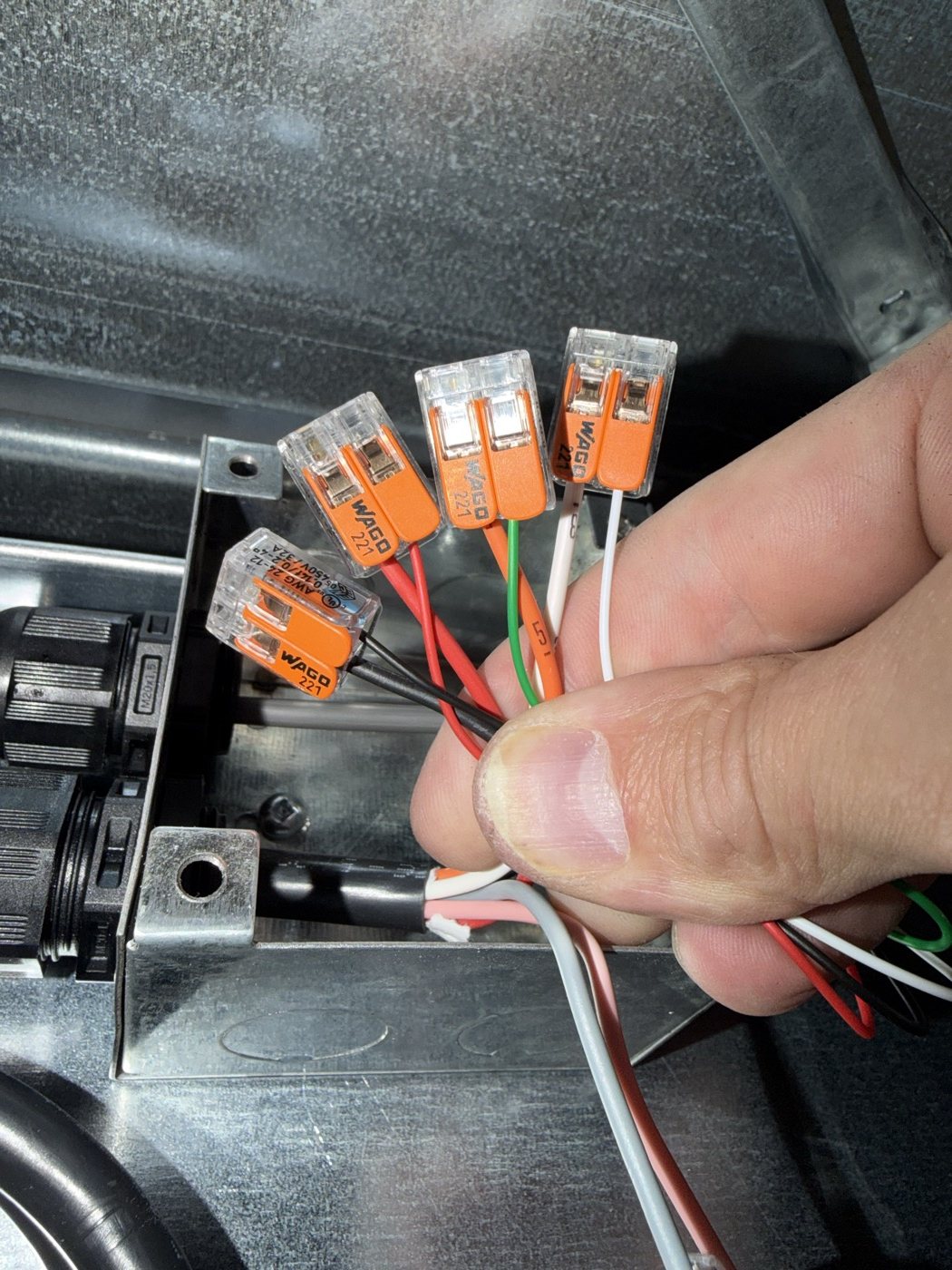
Colour-coding is not the finish line. On this controller type, the Belimo datasheet lists the positioning signal Y as selectable between 0–10 V and 2–10 V, and the feedback U as selectable to represent volume flow, damper position or the Δp measured at the unit's own flow sensor. Which one the unit leaves the factory with is on the TROX test documentation that ships with it. If the Trend output is scaled 0–10 V and the controller expects 2–10 V, everything below 20% demand sits at minimum and the airflow lags the demand all the way up — at 50% demand you get 37.5% of span. Get it the other way round and the unit never gets back down to its minimum. And if the Trend thinks U is airflow when it's actually damper position, the graphics will show a number that looks plausible and means nothing. We cover the scaling side in more depth in our guide to integrating Belimo VAV actuators with Trend IQ412 controllers.
Why fit CO₂ sensors on the extract duct?
A CO₂ sensor in the extract duct reads the mixed air leaving the zone, so it's a good proxy for how many people are actually on the floor. Feed that into the BMS and the VAVs can be driven by demand rather than by a fixed schedule — demand-controlled ventilation. Full airflow when the floor's full, backed off when it's half-empty, and a record of air quality the landlord can point to.
The Sontay GS-CO2-D uses an NDIR sensing element with an automatic baseline correction (ABC) algorithm, and auto-detects whether the controller input is set to 0–10 V or 4–20 mA on a three-wire connection. That's why this sensor only needed three of the four Belden cores:
| Belden core | Sontay terminal | Function |
|---|---|---|
| Red | 24V | 24 V AC/DC supply |
| Black | GND | 0 V / common |
| White | OUT | CO₂ signal to BMS |
| Green | — | Spare, isolated |
The spare green core is terminated in a lever connector tucked inside the sensor housing, so it's insulated, identifiable and available later — not cut back flush where nobody can use it.
Get a Free BMS Survey
We'll assess your controls and provide a detailed quotation.
What usually goes wrong on a VAV installation?
The most common fault on VAV floors isn't the VAV. It's the assumption that factory-configured means site-ready. These units are parameterised and aerodynamically tested on the manufacturer's rig, and ship with the test documentation to prove it — but they're parameterised for the order, not for your controller's output card. Signal range, control mode and the meaning of the feedback all need checking against the BMS before anyone signs the floor off.
Mode is the next trap. The LMV-D3 platform supports BACnet MS/TP, Modbus RTU, MP-Bus and analogue control, including a hybrid mode where the setpoint comes in on Y and position feedback goes out over the bus. A unit left configured for bus control on an analogue-only job can sit there ignoring a perfectly good 0–10 V signal. The mode and communication parameters are set with Belimo's ZTH EU service tool or PC-Tool — so someone needs one on site at commissioning, not in the van at another job.
Then there's the cable itself. Belden runs through ceiling voids get pulled in quickly and tied up quickly. BS 7671 (18th Edition), Regulation 521.10.202, requires wiring systems throughout an installation to be supported so they won't collapse prematurely in a fire — plastic ties on their own don't meet that. The regulation exists because collapsed cables entangle firefighters. Use fire-resistant metal fixings at intervals along the route, whatever else is holding the cable. The IET publishes the Wiring Regulations and their guidance notes.
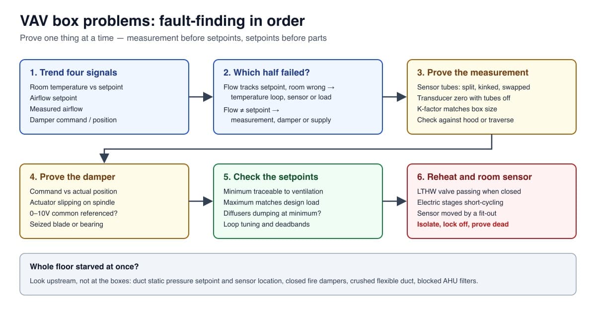
Last, sensors in the wrong place. A duct CO₂ sensor needs to sit where the extract air is mixed and representative of the zone — not tight behind a bend, and not upstream of a take-off from a different space. Get that wrong and demand-controlled ventilation runs on a lie. Our VAV box fault-finding guide goes through the symptoms these problems produce once the floor is occupied.
What standards apply to VAV and CO₂ controls?
Approved Document F 2021, Volume 2 — statutory guidance for England — introduced CO₂ monitoring for new offices: occupiable rooms between 50 m² and 320 m² floor area should have a way of assessing indoor air quality, such as CO₂ monitors. Those monitors should be NDIR type, and Approved Document F's Appendix C gives 800 ppm and 1,500 ppm as guide figures for judging whether a space is adequately ventilated. For design targets, BS EN 16798-1:2019 sets an Annex B default for Category II indoor environments of 800 ppm above outdoor CO₂. CIBSE guidance covers how those figures are applied in practice.
EN 1751 classifies casing air leakage; TROX lists the TA-Silenzio at Class C, which matters on extract where you're trying to measure and control flow accurately rather than lose it through the casing.
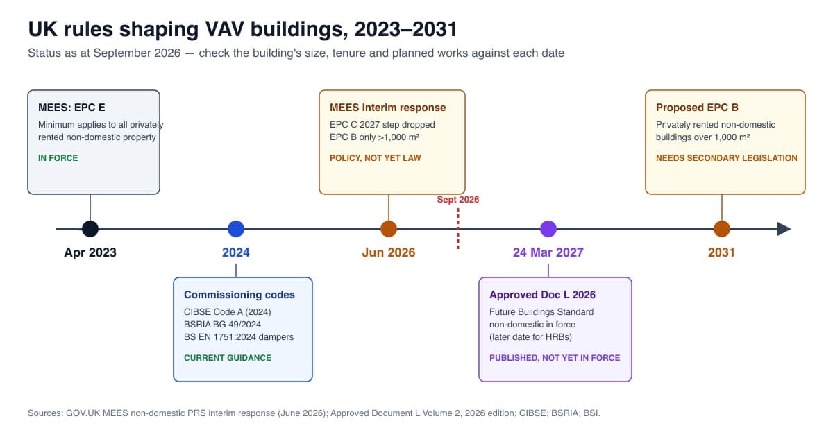
For larger buildings, Approved Document L 2021, Volume 2 says a building automation and control system should be fitted where heating or air-conditioning systems exceed 180 kW effective rated output — in new buildings, and in existing buildings when the BACS is replaced. A VAV floor without working feedback is a BACS that can't report what the plant is actually doing. Our VAV regulations guide covers where that's heading, including MEES.
What does a good VAV installation look like?
A good VAV installation leaves the next engineer nothing to guess. Every VAV has its own home-run Belden to the panel, labelled at both ends with the VAV reference from the TROX label. The adaptable box is glanded, the terminations are lever connectors or proper terminals, the bus cores are insulated individually, and the spare cores are parked and identifiable. The TROX test sheets are kept with the O&M, and the Trend strategy is scaled to the signal range the controller is actually set to — checked, not assumed.
At commissioning, each VAV is driven from the BMS to minimum and maximum and the feedback watched as it moves; each CO₂ sensor is checked against a reference reading. That's the difference between a floor that's been installed and a floor that's been proved. If you want the wider picture of how VAV systems work before you spec one, start with what a VAV system is and how VAV boxes work.
When should the controls contractor be brought in?
The time to get us involved is before the mechanical contractor hangs the units, not after. Once the VAV order is placed, the controller type, control mode and signal range are fixed at the factory — and changing them on site takes a service tool and time. Getting the controls scope agreed at order stage means the units arrive set up for the controller that's actually going to drive them.
If you've got a floor refurbishment coming with new ductwork and VAVs, or an existing VAV floor that's never quite behaved, request a quote or get in touch. We've wired TROX VAVs before at 1 Eversholt Street and worked on VAV controls at 20 Gresham Street, and we'd rather sort it at the design stage than chase it at handover.
VAV installation FAQs
How many cores do you need to wire a VAV controller to a BMS?
Three cores for power and control (24 V, 0 V and the Y control signal), four if you want feedback on U back to the BMS. The pink and grey bus cores are only used for BACnet MS/TP or Modbus.
What are the pink and grey wires on a TROX or Belimo VAV controller?
Wires 6 and 7 are the RS-485 bus pair (C1/D– and C2/D+) for BACnet MS/TP or Modbus RTU. On analogue control they're unused and should be individually insulated.
Is a TROX VAV 0–10 V or 2–10 V?
It can be either. On the LMV-D3 compact controller platform, the Y control signal is selectable between 0–10 V and 2–10 V. Check the TROX test documentation for the factory setting before scaling the BMS output.
Why put a CO₂ sensor in the extract duct?
Extract air is mixed room air, so its CO₂ level reflects occupancy. The BMS uses it to run demand-controlled ventilation — more air when the floor is busy, less when it isn't.
Do Sontay CO₂ sensors need four wires?
No. The Sontay GS-CO2-D is three-wire (24 V, GND, OUT) and auto-detects a 0–10 V or 4–20 mA input. A fourth core can be left as an isolated spare.
Alpha Controls Team
Specialist BMS installation, commissioning, and maintenance across London and the South East. SafeContractor Approved, BCIA Member.