
A VAV (variable air volume) system cools and ventilates a building by keeping the supply air temperature roughly constant and varying how much air each zone receives. Each zone has a VAV box: a flow sensor, a motorised damper and a controller that moves the damper to hold the airflow the room needs, so the AHU fan can slow down.
Picture a common scenario. An FM manager takes over a 1990s office block. The north side of the third floor is freezing, the south side is roasting, the air handling unit fan is flat out at 100% all day and the energy bill has crept up every year since the last refurb. Somebody has written "VAV" on the O&M manual cover, nobody on site really knows what that means, and the last controls contractor left a front end full of boxes showing zero airflow. VAV is a good system, but it is a system: the air handling unit, the ductwork, dozens or hundreds of terminal boxes and the BMS all have to agree with each other, and when one part drifts the whole floor feels it. This guide explains what a VAV system is, how a VAV box works, where it goes wrong and what good looks like, from the point of view of the people who commission and fix them.
What is a VAV system?
A variable air volume system is an all-air HVAC system in which a central air handling unit (AHU) supplies conditioned air at a fairly steady temperature into a ductwork network, and terminal units in each zone vary the volume of that air to match the zone's load. More heat in the room means more cool air; less heat means less air. The alternative it replaced, constant air volume (CAV), does the opposite: it moves the same volume of air all the time and changes the temperature of that air to suit the load, which means the fans never get a rest.
The energy argument follows from how fans behave. Under the fan affinity laws, the power a fan absorbs rises roughly with the cube of its speed, so a fan running at 80% speed needs in the region of half the power it draws at full speed. Real systems rarely get the full theoretical saving, because the fan is working against a duct pressure setpoint rather than a free system curve, but the direction is the whole point of VAV: a building spends most of its occupied hours well below design load, and a VAV system lets the supply fan follow that load down instead of pushing design airflow around an empty office.
In the UK, fan coil units and chilled beams took a large share of the office market, so VAV is less familiar to many FM teams than it is to engineers who trained on American plant. It is still widely installed. Plenty of London office stock from the 1980s to the 2000s runs on VAV, it appears regularly in laboratories and healthcare where airflow has to be measured and proved, and it comes back into fashion whenever a design team wants all-air ventilation with good turndown. If you are weighing it up against other systems, our guide to why modern buildings need both AHUs and FCUs covers the ventilation-versus-comfort split that sits underneath the choice.
How does a VAV box work?
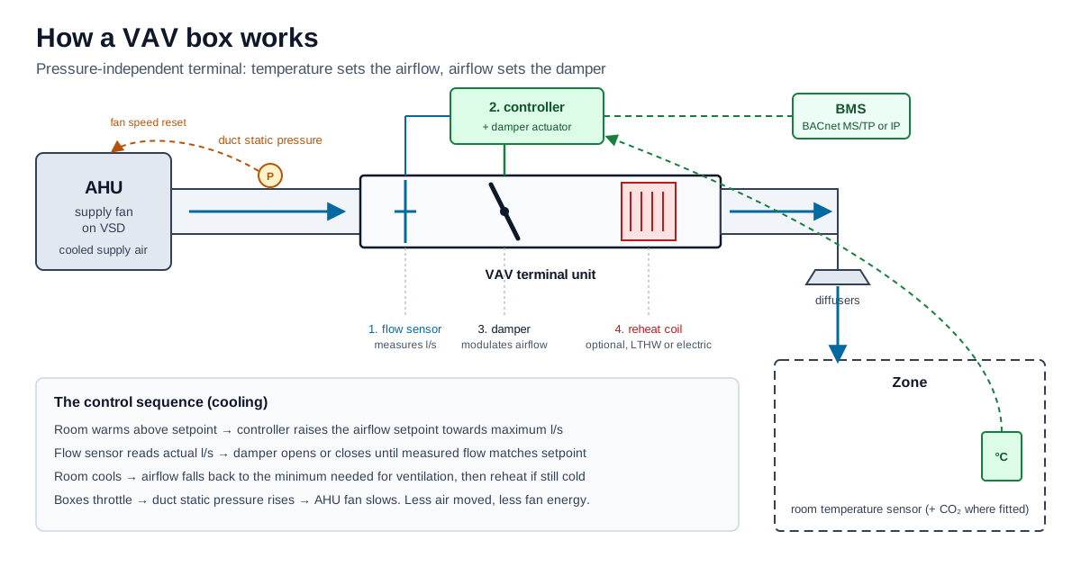
A VAV box, also called a VAV terminal unit, is a short section of insulated ductwork fitted in the ceiling void between the branch duct and the diffusers. Inside it there are four working parts. At the inlet sits a flow sensor, usually a cross or ring of tubes with holes facing into and away from the airstream, which produces a small differential pressure, the velocity pressure, that rises with the square of the air velocity. Behind that is a damper, a single blade on a spindle, driven by an actuator. Mounted on the side is the controller, which on most modern boxes is a single device combining the actuator, a differential pressure transducer and a BACnet or proprietary controller. Downstream there may be a reheat coil, either an LTHW coil with a two-port valve or an electric heater battery, for zones that need heating.
The controller converts the flow sensor's differential pressure into airflow using a box-specific calibration constant, commonly called the K-factor. The relationship is a square root one: airflow equals K multiplied by the square root of the measured velocity pressure. That is why the K-factor matters so much. Get it wrong by a few percent and every airflow reading on that box, and every airflow setpoint the BMS thinks it is achieving, is wrong by the same margin. The terminal unit manufacturer publishes the flow sensor constant for each box size (a K-factor, or a nominal flow setting on many European compact controllers), and the air balancing contractor proves it on site.
The sequence on a standard cooling-only zone is a cascade of two control loops. The outer loop compares the room temperature with its setpoint and produces an airflow setpoint somewhere between the box's minimum and maximum. The inner loop compares that airflow setpoint with the measured airflow and drives the damper until they match. When the room warms up, the airflow setpoint rises and the damper opens; when it cools down, the airflow setpoint falls back towards minimum. If the room is still too cold at minimum airflow and the box has reheat, the controller brings the reheat coil in.
What is the difference between pressure-independent and pressure-dependent VAV?
A pressure-independent VAV box measures airflow and controls to an airflow setpoint, which is the cascade described above. Because it is measuring the actual air coming through, it does not care whether the duct pressure upstream rises or falls: if a neighbouring box closes and the branch pressure rises, the flow loop closes this damper slightly to hold the same l/s. Pressure-independent control is the norm on modern commercial VAV installations, and it is the only type that can prove a ventilation rate to a room.
A pressure-dependent box has no airflow measurement. The room temperature loop drives the damper position directly, so the airflow at any given damper position depends on the duct pressure at that moment. When the whole floor calls for cooling at the same time, the pressure drops and every zone gets less air than it expects; when most zones are satisfied, the pressure rises and the remaining open boxes get more than they need. You still find pressure-dependent control on older and simpler installations, and on retrofits where the flow sensor tubes have been blocked, broken or simply never connected. On the front end, a box that reports a damper position but no airflow is often telling you exactly that.
Get a Free BMS Survey
We'll assess your controls and provide a detailed quotation.
What are VAV minimum and maximum airflow setpoints?
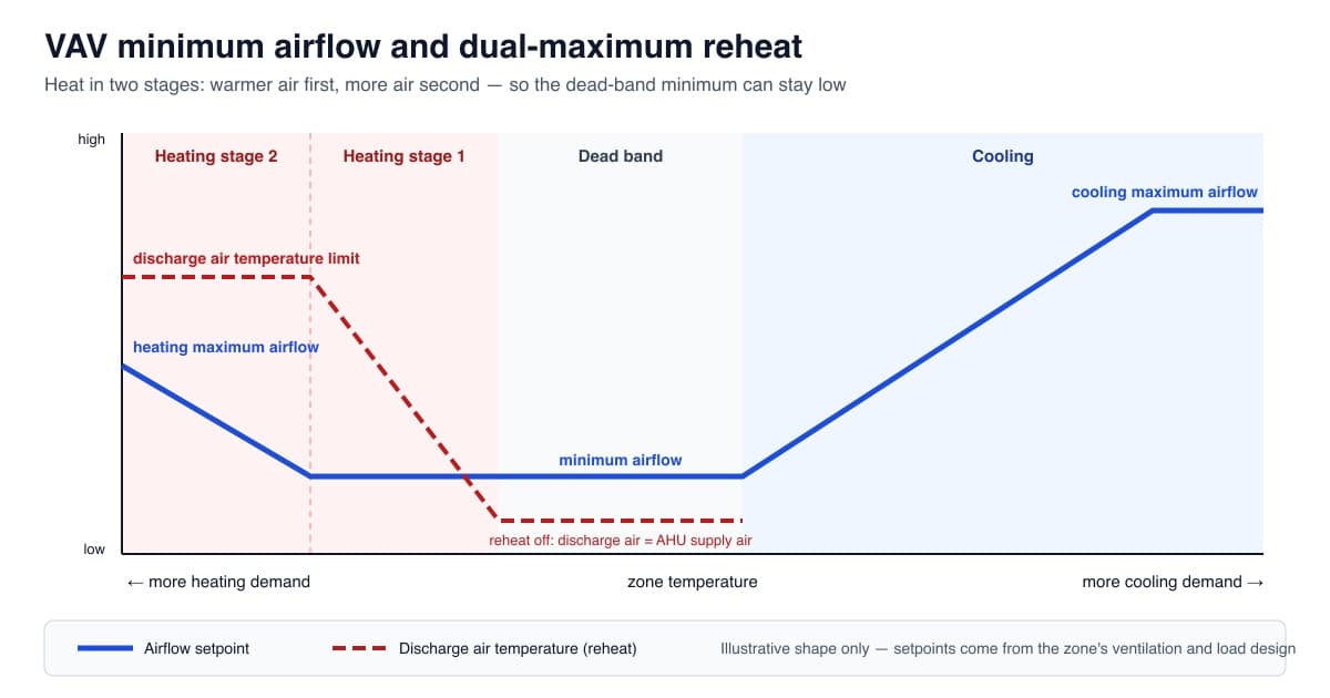
Every VAV box is set up with a maximum airflow, sized to meet the zone's design cooling load, and a minimum airflow, which is the least air the box will ever supply while the zone is occupied. The minimum is where most of the engineering judgement sits. Set it too high and the box over-cools the zone at light load, the reheat coil fights the cold air, and the fan never turns down, which undermines the energy case for VAV. Set it too low and the zone may not receive enough outdoor air, diffusers can "dump" cold air straight down onto desks because the discharge velocity is too low to hold the air to the ceiling, and on some boxes the flow sensor signal becomes too small to measure reliably.
Where the VAV system is also the ventilation system, the minimum has to deliver the zone's share of outdoor air. For occupiable rooms in offices in England, Approved Document F Volume 2 (paragraph 1.32) asks for outdoor air at 10 l/s per person or 1 l/s per m² of floor area, whichever is higher, and the AHU's outdoor air fraction together with the box minimums is what actually delivers it at the diffuser. That link is the reason minimum airflow setpoints must never be "tuned down" on the front end to save energy without somebody checking the ventilation calculation first. We cover the heating side of the same problem, including dual-maximum reheat sequences, in our guide to VAV minimum airflow and reheat control.
How does the AHU know how fast to run?
The AHU supply fan on a VAV system is on a variable speed drive, and the BMS normally controls its speed to hold a duct static pressure setpoint measured by a sensor out in the supply duct. As boxes close, duct pressure rises and the fan slows; as boxes open, pressure falls and the fan speeds up. The sensor location and the setpoint are both critical. A sensor fitted right next to the AHU outlet, or a setpoint chosen on the hottest day of commissioning and never revisited, is a common reason for VAV fans running far faster than the building needs.
The better approach is to reset the static pressure setpoint from what the boxes are actually doing, lowering it until the zones that need the most pressure are only just satisfied. ASHRAE Guideline 36 does this with request-based "trim and respond" logic. Alongside fixing minimum airflows and reheat, it is often one of the largest energy improvements available on an existing VAV system, and it rarely needs new hardware. Our guide to VAV static pressure reset and trim and respond sets out how it works and where it goes wrong. If the fan drive itself is tripping, that is a different problem, and our AHU fan VSD fault-finding guide is the place to start.
VAV vs CAV vs fan coil units: what is the difference?
The three systems solve the same problem in different ways, and the choice affects everything from ceiling void depth to how the BMS is structured. The comparison below is how we explain it to clients who are inheriting or refurbishing a building.
| Feature | VAV (variable air volume) | CAV (constant air volume) | Fan coil units (FCU) |
|---|---|---|---|
| What varies with load | Air volume to each zone | Supply air temperature | Coil output and local fan speed |
| Where the cooling comes from | Central AHU coil | Central AHU coil | Chilled water coil in each unit |
| Fresh air | Delivered through the same boxes | Delivered with the supply air | Needs a separate AHU and ductwork |
| Fan energy at part load | Low: AHU fan turns down | High: fan runs at design volume | Many small fans plus AHU |
| Kit in the ceiling void | Terminal boxes, larger ductwork | Ductwork only | FCUs, water pipework, condensate drains |
| Water in the ceiling | Only if LTHW reheat is fitted | Only if terminal reheat is fitted | Yes, chilled and often LTHW |
| Typical BMS points per zone | Airflow, damper, room temp, reheat | Few: control is central | Room temp, valves, fan speed, condensate |
Each has its place. VAV wins on fan energy and on proving airflow, CAV survives where airflow must stay fixed regardless of load, and fan coils win where ceiling voids are shallow and zones change often. On a mixed estate, what matters more than the system type is whether its controls strategy actually matches how the building is used today.
What usually goes wrong with VAV systems?
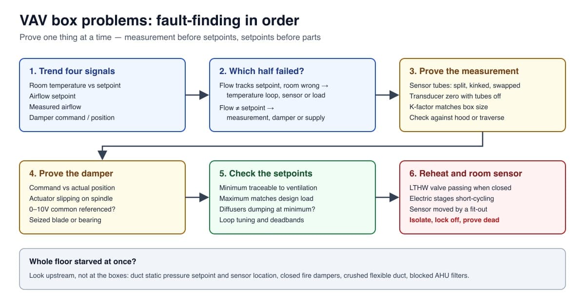
After enough plant rooms and ceiling voids, the same faults come round again and again, and very few of them are the box itself. The most common is simply lost calibration: K-factors that were never set, flow sensor tubes that have split or been disconnected during a fit-out, or pressure transducers that have drifted after twenty years so that a box reporting 200 l/s is really delivering 120. Close behind are minimum setpoints that were raised years ago to cure a stuffiness complaint and never put back, which leaves the reheat fighting cold air all winter. Then there are the fit-out problems, where a Cat A or Cat B contractor has moved partitions so that one box now serves two rooms and the room sensor sits in the wrong one.
Reheat is the other big one. Engineer forums are full of reheat questions, from LTHW valves passing so that the coil heats all year to electric reheat stages whose relays or contactors fail early because the control loop cycles them on and off far too often. Electric reheat also brings a safe isolation problem: the heater section of a VAV box carries mains voltage in a ceiling void, and it has to be isolated, locked off and proved dead before anyone opens it, whatever the programme says. Our practical VAV box problems fault-finding guide works through each of these in order.
Which standards and guidance apply to VAV systems in the UK?
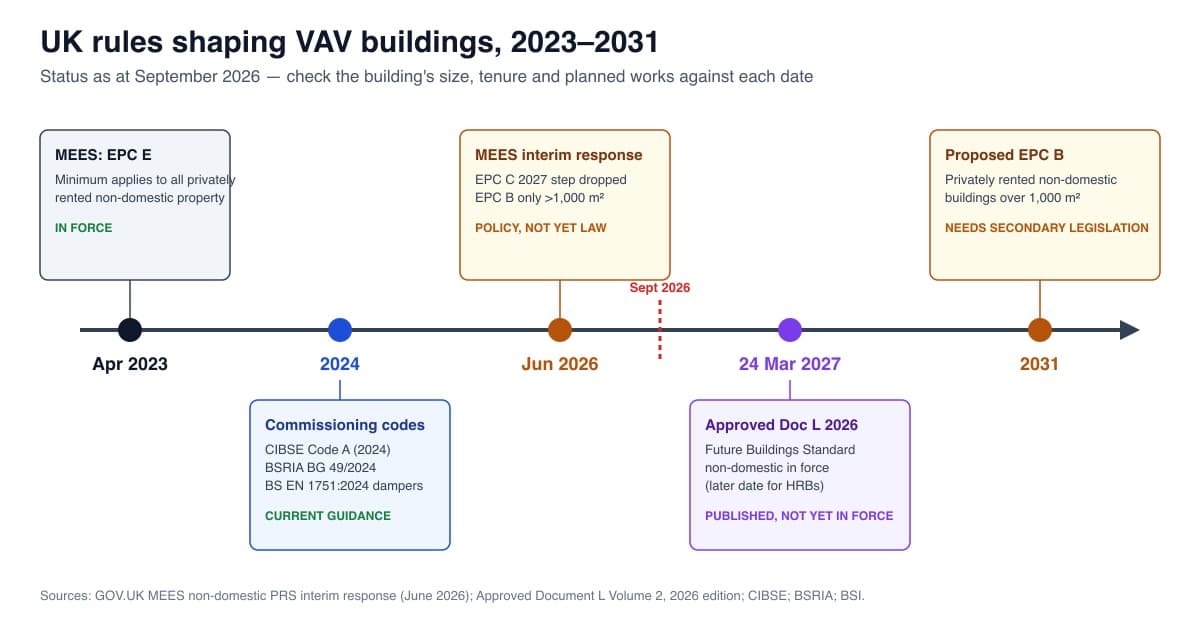
Several documents govern how a VAV system should be designed, commissioned and maintained in the UK, and two of the most important were refreshed recently. CIBSE Commissioning Code A: Air distribution systems was revised in 2024, alongside BSRIA BG 49/2024 Commissioning Air Systems, which replaced the 2015 edition and gives the practical procedures for setting to work, regulating and functionally testing air systems in line with the Code. For damper performance, BS EN 1751:2024 is the current edition of the test standard for dampers and valves, including how air leakage past a closed damper is measured and classified, which matters on a VAV box because a leaky damper at minimum position adds uncontrolled air to the zone.
On the regulatory side, in England, Approved Document F Volume 2 is the statutory guidance on the ventilation rates needed to meet Part F of the Building Regulations, and Approved Document L Volume 2 governs fan power, controls and building automation for work on non-domestic buildings; its current 2021 edition, for example, says fans for general air distribution rated above 1100 W should have variable speed drives (paragraph 6.49). The next edition of Approved Document L Volume 2, which implements the Future Buildings Standard, has been published and is due to take effect on 24 March 2027. The detail, along with where MEES has landed after the June 2026 government update, is in our guide to VAV systems and UK regulations in 2026. For the control sequences themselves, ASHRAE Guideline 36-2024 (High-Performance Sequences of Operation for HVAC Systems) is the most complete published reference, and while it is an American document, its VAV zone and AHU sequences can be adapted for UK projects.
What does a well-run VAV system look like?
A VAV system that works has a few things in common, whatever make the boxes are. Every box has a verified K-factor and a recorded commissioning airflow at minimum and maximum. The minimum airflows are traceable back to a ventilation calculation rather than to whoever last received a complaint. The AHU static pressure setpoint is reset from box demand rather than fixed. The BMS trends room temperature, airflow setpoint, measured airflow and damper position for every box, so that a box sitting at 100% damper while short of airflow, or at 0% while still over-cooling, flags itself instead of waiting for a tenant to ring. And the graphics show the whole chain on one page, from AHU fan speed to the worst zone, so an engineer can see in one glance why the fan is running where it is.
Real installations follow the same pattern. At 20 Gresham Street in the City of London, the BMS Alpha Controls installed uses Automated Logic controllers on a BACnet/IP backbone to manage fan coil units, VAV boxes and environmental plant, with each floor divided into four control zones and plant and metering data routed back to the main BMS panel for monitoring and trending. Older systems are where it tends to fall down. On a seven-floor VAV office in central London, the retrofit in our guide to integrating legacy Belimo VAV actuators with Trend IQ412 controllers kept Belimo actuators that had run reliably for nearly twenty years, and the guide explains why adding position feedback is worth doing, so the BMS can tell a damper that was commanded open from one that actually is. The field network matters too: a large MS/TP network of VAV controllers will only be reliable if segment loading, repeaters and end-of-line termination are right.
When should you get a VAV system looked at?
There are some clear triggers. If the AHU supply fan runs above about 90% for most of the occupied day, if more than a handful of boxes show zero or implausible airflow on the front end, if hot and cold complaints cluster on particular floors or elevations, or if reheat is running in July, the system is telling you it has drifted. A fit-out that has moved partitions, a change of tenant, an EPC or MEES review, or a controller platform reaching end of life are all good moments to recommission the air side properly rather than patching individual complaints. Our guide to the signs a BMS needs recommissioning covers the wider picture.
VAV is a well-proven way to condition a building with the fans doing only as much work as the load needs, but only when the boxes, the AHU and the BMS are set up as one system and kept that way. Alpha Controls installs, commissions, upgrades and maintains VAV controls on Trend, Distech and Siemens systems and other open-protocol platforms across London and the South East. If you have a VAV system that is not behaving, or you are planning an upgrade, talk to our engineers or request a quote and we will start with a survey of what is actually installed.
Frequently asked questions about VAV systems
What does VAV stand for in HVAC?
VAV stands for variable air volume. A VAV system supplies air at a fairly constant temperature and varies the volume delivered to each zone to match its load, using a VAV box with a flow sensor, damper and controller in each zone.
How does a VAV box know how much air to supply?
The controller compares room temperature with setpoint to produce an airflow setpoint between minimum and maximum, measures actual airflow with a flow sensor using the box's K-factor, and drives the damper until measured airflow matches the setpoint.
What is the difference between VAV and CAV?
A VAV system varies the air volume and keeps supply temperature roughly constant, so the AHU fan slows at part load. A CAV system keeps the air volume constant and varies supply temperature, so the fan runs at design airflow all the time.
Is VAV better than fan coil units?
Neither is better everywhere. VAV has low fan energy at part load, no chilled water in the ceiling and measurable airflow per zone. Fan coils suit shallow ceiling voids and frequently changing layouts but need a separate fresh air system.
Does a VAV box need a minimum airflow?
Yes. The minimum must deliver the zone's ventilation air where the VAV system carries it, keep diffusers throwing air along the ceiling, and stay above the controller's minimum measurable airflow. It should be set from those limits, not a flat percentage.
Who commissions and maintains VAV controls in London?
Alpha Controls installs, commissions, upgrades and maintains VAV controls on Trend, Distech and Siemens systems and other open-protocol BMS platforms across London and the South East, starting with a survey of what is actually installed.
Alpha Controls Team
Specialist BMS installation, commissioning, and maintenance across London and the South East. SafeContractor Approved, BCIA Member.