
An ABB ACH580 reporting Fault 3381 — Output phase loss / Missing motor connection does not automatically mean the motor or the drive has failed. On a recent callout to a central London commercial building — a duty/standby pair of office extract fans, each on its own ACH580 and Brook Crompton motor — the fault turned out to be neither a dead motor nor a dead drive. The winding configuration inside the motor terminal box was causing the drive to see abnormal output conditions. This case study reconstructs the investigation, step by step, from the evidence on site and explains why methodical testing matters more than the code on the keypad.
The central lesson is simple enough to write on a panel door: a fault code tells you what the equipment has detected, not what has actually gone wrong. The engineering value is in how you get from one to the other without replacing things that are not broken.
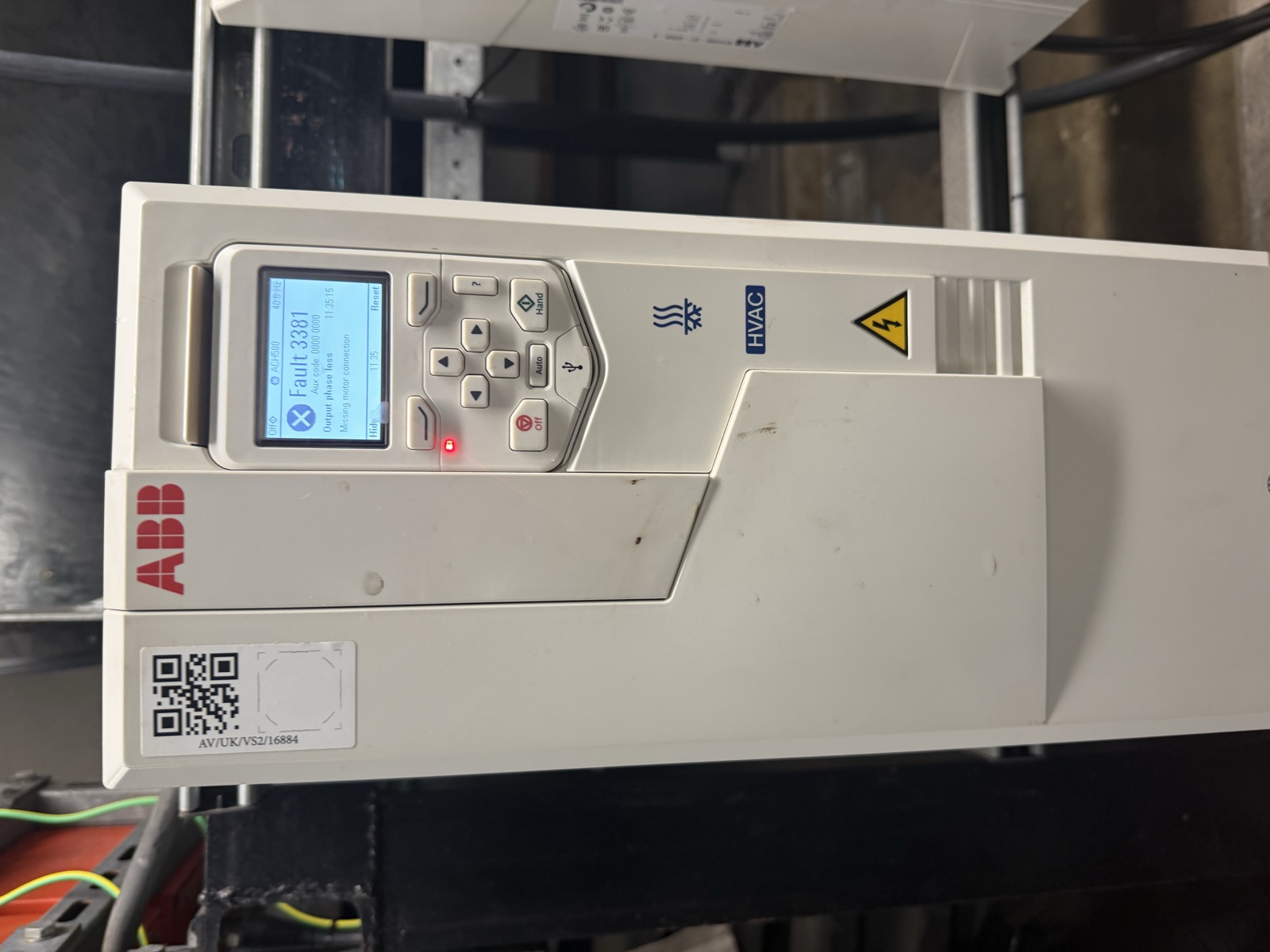
ABB ACH580 displaying Fault 3381 — Output phase loss / Missing motor connection, as found on the callout. The auxiliary code read 0000 0000 and the reference frequency showed 40.0 Hz.
Safety note. Work described involved three-phase mains voltage, VSD output circuits and stored DC-bus energy inside the drive. All testing and terminal reconfiguration was carried out with the system safely isolated and proven dead, with the drive allowed to discharge in accordance with the manufacturer's requirements — the drive itself carries a yellow label requiring a five-minute wait after disconnection. Do not remove drive covers, alter motor terminal links or work on live equipment unless you are qualified and following the manufacturer's and site safety procedures.
The callout: duty fan not running
The building operates a pair of axial extract fans for the office cores — labelled Core No.3 Office Extract Fan No.1 (F1, 15 kW, duty) and No.2 (F2, 15 kW, standby) on the panel doors. The duty fan had stopped providing service. The associated ACH580 showed a latched Fault 3381 and its red fault LED was lit. The neighbouring standby — mechanically unloaded at the time — was available as a known-good comparison and was running normally.
That pairing mattered: it gave us a second, identical drive and motor we could use as a comparator rather than guessing what "normal" should look like on this system.
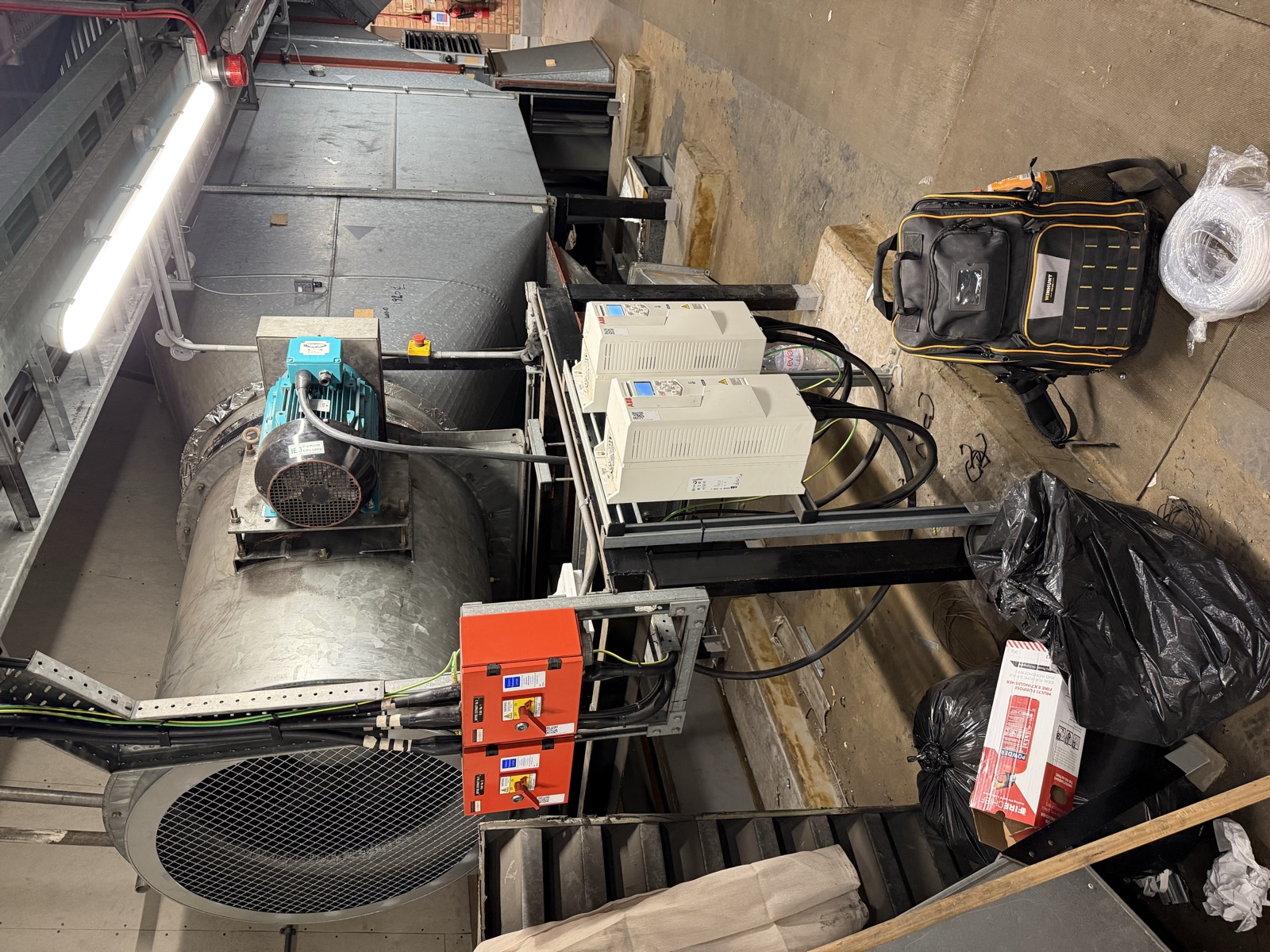
The plant room arrangement — two ABB ACH580 drives serving the duty/standby pair, with the Brook Crompton motor mounted on the Woods axial fan casing. The local isolators are visible below the fan.
What ABB ACH580 Fault 3381 actually means
ABB documents Fault 3381 as Output phase loss — all three phases are not connected to the motor, also described in the ABB hardware/firmware guides as a motor circuit fault due to a missing motor connection (all three phases are not connected). It is a fault (not a warning) and the keypad presents it as "Output phase loss / Missing motor connection".
In other words, the drive has detected that it does not have a normal three-phase motor circuit on its output — the drive's output current sensing cannot see the three phases it expects. That description matters: 3381 is not an incoming-supply fault (ABB's incoming phase concept is a different code) and it is not, by itself, a diagnosis of a failed winding or a failed drive. It is a report of what the drive measured on its output.
The textbook remedies in the ABB literature are correspondingly generic — connect the motor cable, check the motor and motor cable including phasing and delta/star connection, and check the motor data in parameter group 99 against the nameplate. The actual root cause still has to be found on site.
Checking the three-phase supply
Before looking downstream, the incoming supply to the affected ACH580 was verified at the drive's input terminals (L1, L2, L3). The three line-to-line voltages were present at approximately 415 V L1–L2, 415 V L2–L3 and 415 V L3–L1.
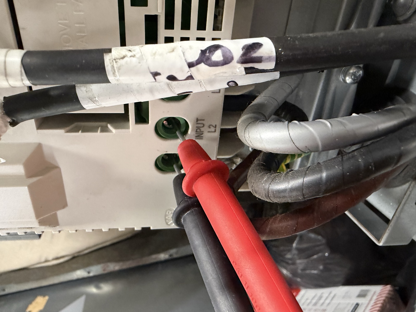
Testing the incoming supply at the drive input terminals (L2 area shown). This photograph confirms where the test was made; the ~415 V line-to-line results are from the live fault-finding record.
That check was useful because it moved the investigation away from an incoming phase-loss hypothesis and towards the VSD output and motor circuit. It does not, on its own, prove every possible upstream condition — but with all three line voltages present at the drive, the output/missing-motor path became the logical next step.
Get a Free BMS Survey
We'll assess your controls and provide a detailed quotation.
The motor circuit: what the first resistance checks showed — and what they did not
With the system safely isolated and proven dead, and with the DC bus allowed to discharge per the drive's warning label, the motor conductors were disconnected from the VSD output. That matters: the resistance checks described below were made independently of the drive electronics, on the motor circuit alone.
Initial phase-to-phase resistance readings on the connected suspect motor circuit (still with its external links as found) were unusual and inconsistent. The values recorded were approximately U–V 0.2 Ω, V–W approximately 0.0 Ω and U–W approximately 0.0 Ω.
Those values need careful handling. At fractions of an ohm, an ordinary handheld multimeter's resolution, probe contact resistance and the parallel paths through interconnected delta windings all limit what can be concluded. No single low-ohm reading at this level is a precision measurement of the winding itself. The readings were useful diagnostically because they were inconsistent enough — including near-zero between two pairs — to prompt a closer look inside the motor terminal box, rather than because they proved a particular winding fault on their own.
A useful comparator: the standby motor
The neighbouring standby motor provided a practical known-good reference on the same job. Its three phase-to-phase readings, taken the same way, were consistently around 0.5 Ω on each pair.
That figure is not a universal "correct" resistance for this type of motor. It was simply the measured value on this installation and a helpful comparator: a consistent set on one motor made the inconsistent, near-zero set on the other harder to dismiss. It also strengthened the case for investigating the suspect motor's terminal arrangement in detail.
The motor on the nameplate
The suspect motor was identified from its plate as a Brook Crompton WP–DA160LU–IE3, 15.0 kW, 400/690 V Δ/Y, 28.3/16.4 A, 1475 r/min at 50 Hz, IP55, Class F, duty S1, IE3 92.1%. The same plate carries the 60 Hz rating (17.3 kW, 460 Δ, 28.3 A, 1770 r/min) and the remaining data: cos φ 0.83, Amb 40 °C / Rise 80 K, IC 411, Wt 98 kg, year 2019.
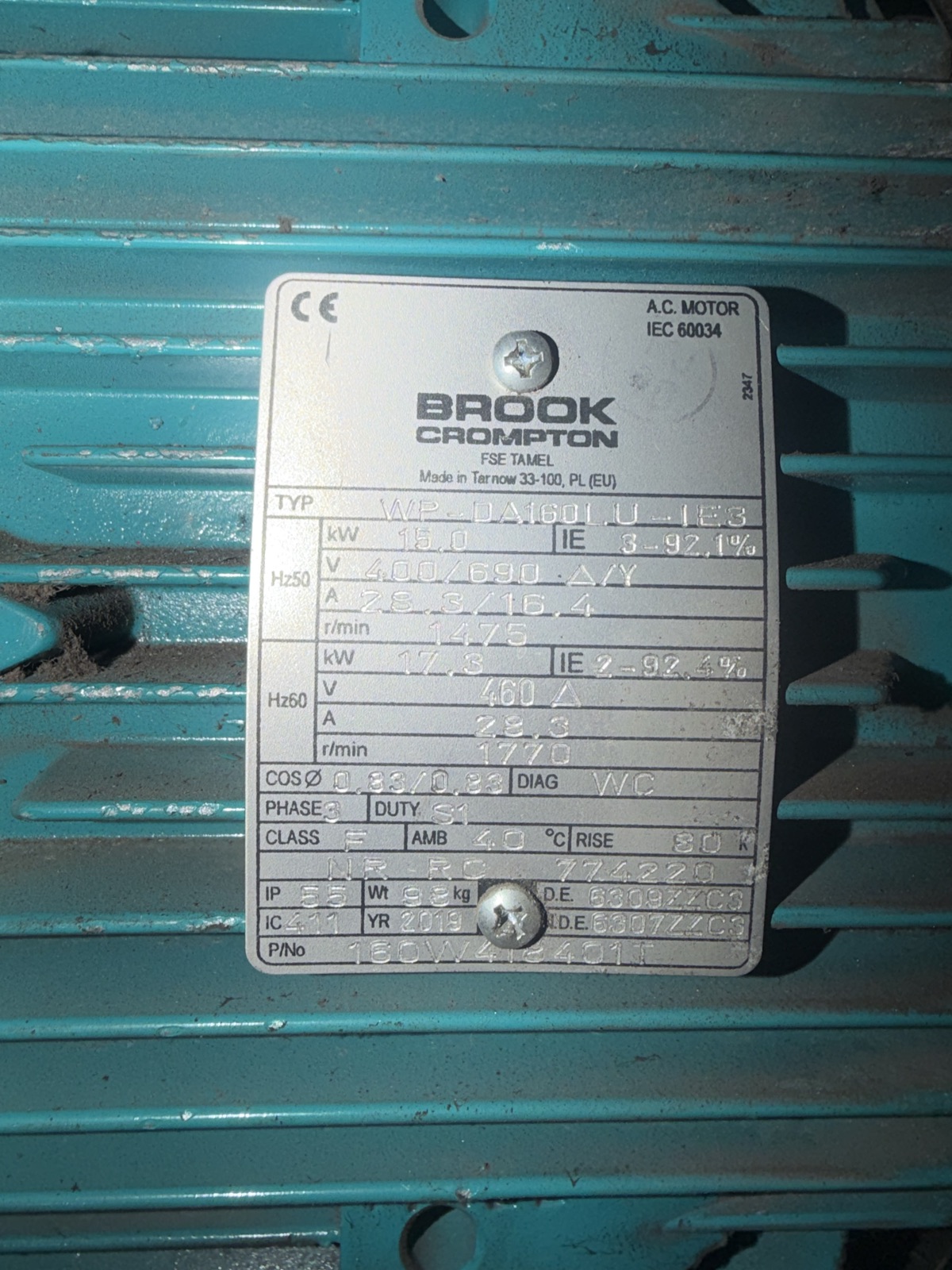
The Brook Crompton nameplate — 15.0 kW, 400/690 V Δ/Y, 28.3/16.4 A, 1475 r/min (50 Hz). For a ~415 V UK supply, delta is the correct configuration for this voltage class — consistent with the plate and Brook Crompton's published guidance for 4 kW and above (400/690 V).
The voltage marking matters: 400/690 V Δ/Y means delta at ~400 V and star at ~690 V. On a UK ~400–415 V supply this motor needs its windings in delta, subject always to the manufacturer's data on the plate. Brook Crompton's W-Aluminium catalogue (20112E) describes the same rule — up to 3 kW 230/400 V, 4 kW and above 400/690 V — which places this 15 kW frame firmly in the 400/690 group; the Installation & Maintenance sheet (103-4E) covers the terminal-box and connection-diagram requirements.
A second plate on the fan casing (Woods of Colchester, reference F4, 415 V 3-phase 50 Hz) confirmed the system voltage class. The fan itself was an axial unit with a finger guard on the inlet; the motor carried an IE3 Premium Efficiency cowl label consistent with the nameplate efficiency marking.
Testing the windings individually
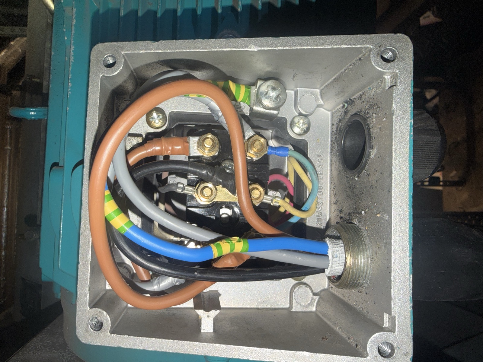
The decisive test was to separate the delta interconnections so the three individual windings could be measured independently. The motor's six studs are marked — top row W2 | U2 | V2, bottom row U1 | V1 | W1 — the conventional terminal layout for an IEC-marked six-stud board. With the external brass links removed and the supply tails pulled back and taped, each winding was tested in turn.
With the external delta links removed, each individual winding could be tested independently. The supply tails are pulled back and taped; the six studs are accessible.
Each winding measured approximately 0.5 Ω — balanced across all three.
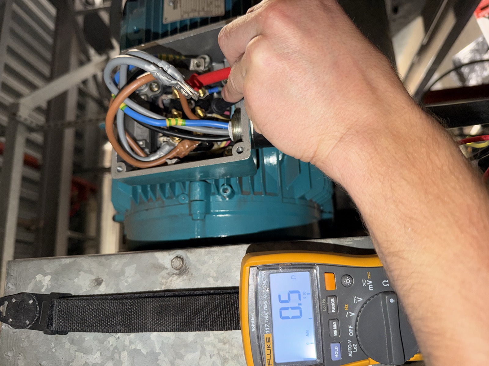
One of the three individual-winding measurements — a Fluke 117 reading approximately 0.5 Ω. A second winding in the set read 0.6 Ω on the same instrument and range; the 0.1 Ω difference is within the handheld low-ohm method tolerance (lead resistance, probe contact and the 6 Ω auto-range shown below the display).
Two photographs of this step are on file: one display shows 0.5 Ω and the other shows 0.6 Ω. That 0.1 Ω spread is entirely consistent with handheld low-ohm practice and does not change the engineering conclusion. The point of the test was not to claim a precision winding value, but to establish — within the limits of the method — that the windings were balanced and not open-circuit. There was no evidence from this test of an open winding or an obvious resistance imbalance.
Equally important is what this test does not prove. Winding resistance alone cannot establish insulation condition, mechanical condition or loaded behaviour. The result is defensibly worded as: no evidence from this test of an open winding or obvious winding imbalance. It is not a claim that the motor was proven electrically perfect in every respect.
The existing terminal arrangement
With the windings shown to be balanced and intact, attention returned to how the external links had been arranged.
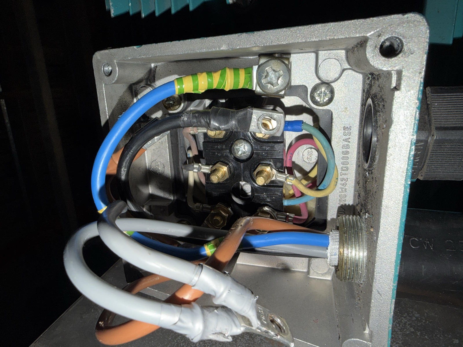
The motor terminal box as first opened — six studs with brass link strips and the supply cores. The link type (brass strip) is clearly visible; the exact incorrect topology is obscured by cable overlap in the photograph, so the chronology and topology are described here from the live fault-finding record rather than from the photograph alone.
The existing arrangement suggested that the winding links had previously been altered, potentially during work associated with reversing the fan/motor arrangement — the assembly had been physically turned through approximately 180 degrees during earlier works. An attempt appears to have been made to obtain the required direction by altering the motor terminal interconnections rather than by maintaining the correct delta configuration and changing phase sequence.
That is a reasonable inference from the combination of (a) the 180-degree reorientation, (b) the incorrect links as found, and (c) the fact that correcting the links to the proper delta and then swapping two supply phases restored correct rotation. The photographs alone do not prove who carried out the earlier modification, when it was done, or exactly what they intended — so the case study is careful not to attribute the previous arrangement to a specific electrician or contractor.
Restoring the correct delta configuration
Based on the board marking Top W2 | U2 | V2 — Bottom U1 | V1 | W1, the appropriate delta interconnections for ~415 V operation were restored as:
- W2 ↔ U1 (left column, vertical)
- U2 ↔ V1 (middle column, vertical)
- V2 ↔ W1 (right column, vertical)
On this board those three links appear as vertical brass strips, one per column, with the supply landed on the linked nodes. The configuration is consistent with the nameplate (400/690 V Δ/Y) and Brook Crompton's published Euro-voltage guidance for this frame and voltage class. For the terminal-by-terminal explanation of star, delta and the six-stud board layout, see three-phase motor wiring: star, delta and six-terminal connections explained.
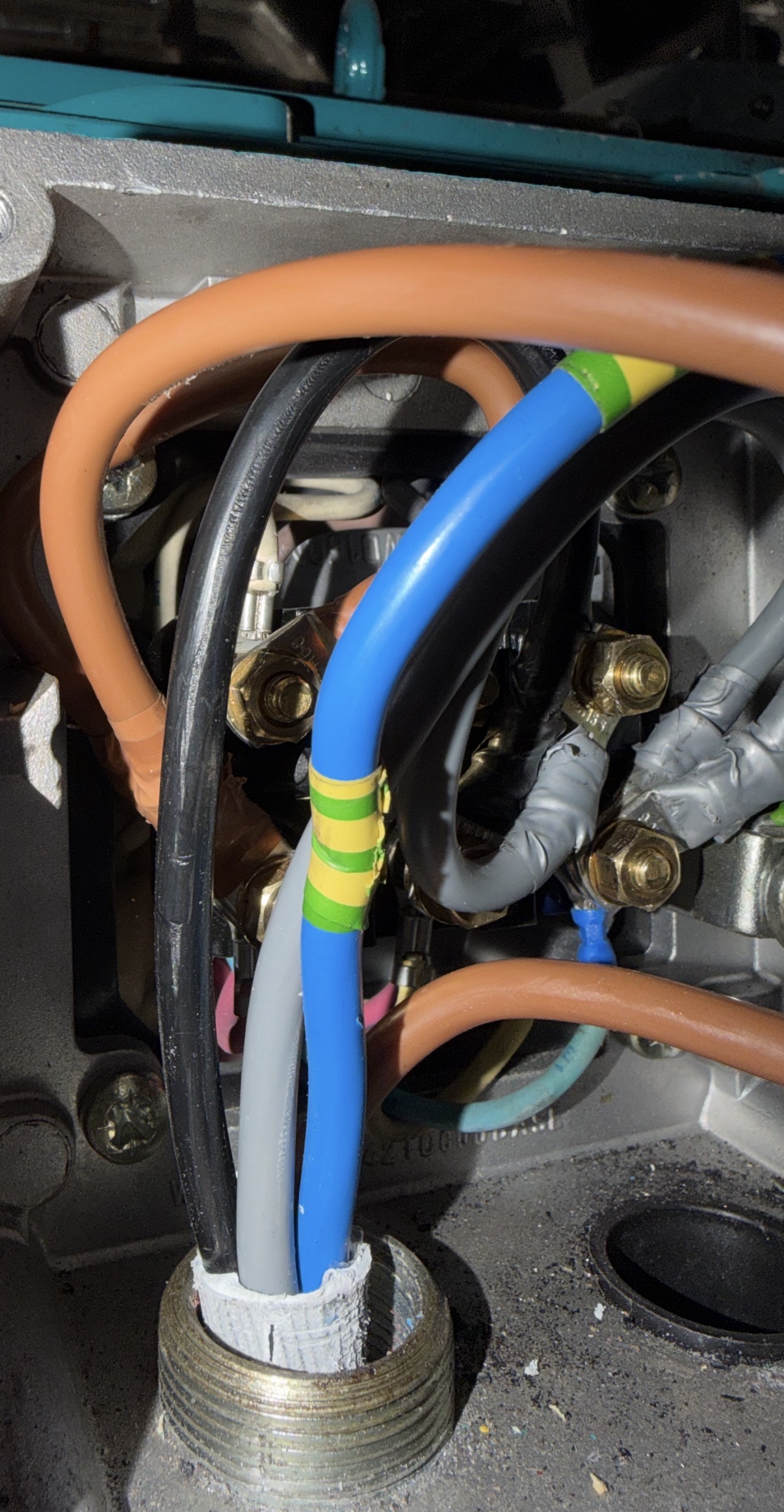
The terminal box with the correct delta configuration restored and the motor circuit reconnected — the supply cores enter through the gland and are terminated on the linked studs (W2↔U1, U2↔V1, V2↔W1). The link positions sit largely behind the cable bundle in this view; the interconnections are as listed above.
Getting the rotation right — on the drive, not at the motor links
With the winding configuration correct, the other half of the job was rotation. Reversing a three-phase motor is done by swapping any two phases in the supply — not by altering winding links, which determine the configuration for the voltage and application. The general method — where the swap is made on DOL, star-delta and drive-fed motors, and what it does to airflow — is in our guide on how to reverse a three-phase motor on an AHU fan.
In this case the required direction was obtained by swapping two phases on the load/output side of the ABB ACH580 — at the drive's motor terminals T1/U, T2/V, T3/W — while leaving the restored delta links undisturbed. There is no photograph of that specific phase swap in the record; the fact that it was done on the drive output is from the live fault-finding notes and is preserved here as such. The work was carried out isolated, proven dead and with the DC bus discharged.
The distinction is worth stating plainly because the earlier incorrect arrangement appears to have confused the two jobs:
- Winding links set the winding configuration for the supply voltage and application.
- Phase sequence (which two phases you swap, and where) sets direction.
Correcting them separately — links for configuration, phase swap for rotation — is the defensible way to leave the motor wired.
Fault cleared — normal operation restored
After the following sequence — identifying the incorrect terminal arrangement; confirming the three windings measured balanced and not open; restoring the correct delta; reconnecting the motor circuit; and correcting rotation with a two-phase swap on the drive output — the motor and fan operated correctly.
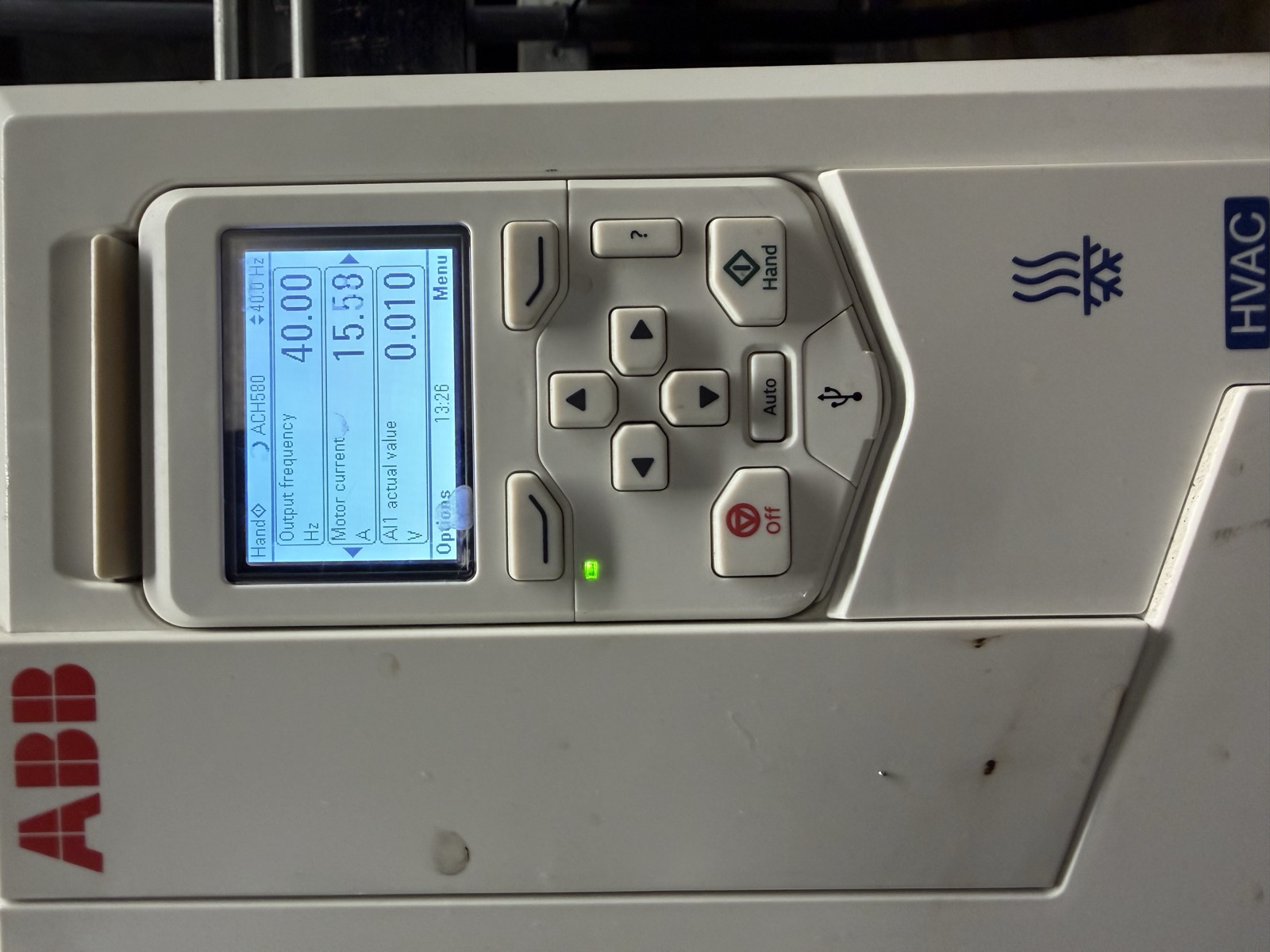
Post-repair — the same ACH580 running in Hand at 40.00 Hz, drawing 15.58 A. The green run LED is lit and Fault 3381 has cleared. Photographed after the terminal-box work and output phase correction above.
The drive ran in Hand at 40.00 Hz, 15.58 A (the single operating point at the moment photographed — not a full-load claim, not the nameplate 28.3 A). Video captured in the interim also shows the pre-repair behaviour: the drive at rest (Off, 0.00 Hz, 0.00 A), a Hand command, and an immediate trip to Fault 3381 at 12:16:46 with the red fault LED lit — confirming that 3381 was a reproducible trip on a run attempt, not a stale latched event. Fault 3381 cleared and normal operation was restored. No replacement VSD and no replacement motor were required.
That last point matters commercially. It would be easy to reach for a new drive on a code that reads "output phase loss" and an existing motor with near-zero phase-to-phase readings. Systematic downstream testing avoided that. No cost saving is invented here — the evidence supports only that the existing drive and existing motor were retained.
What this fault tells you about fault codes
The strongest lesson from this job is not that wires were in the wrong place. It is this:
The drive reported an output phase-loss condition. All three incoming phases were healthy and none of the individual motor windings was open. The winding configuration itself was causing the drive to see abnormal output conditions.
A fault code describes what the equipment has detected. It does not always identify the physical root cause, and in this case the text on the keypad — "missing motor connection" — was true from the drive's point of view (it did not have three normal phases to drive) while being misleading if read as "the motor is not connected."
For facilities and BMS engineers the practical takeaways are below; the same sequence, generalised to any tripping AHU fan drive, is in our AHU fan VSD fault-finding guide. Prove-the-supply-before-condemning-the-device applies equally on the controls side — see tracing a dead Trend IQView4 to a failed UPS.
- Isolate the question. Test the incoming supply at the drive, then test the motor circuit independently of the drive. Separating the two halves of a VSD system is what lets you move the investigation downstream with confidence.
- Use a comparator where you can. A nearby known-good motor (here, a consistent ~0.5 Ω set) is more useful than an absolute value from a table.
- Separate the delta to see the windings. Connected links and parallel delta paths hide open windings and can mask link errors; separated windings make balance (and an open circuit) visible.
- Treat low-ohm readings as diagnostic prompts, not precision proofs. At fractions of an ohm, probe contact and range selection matter. Let the readings tell you to open the terminal box — then let the terminal box tell you what is actually wrong.
- Keep configuration and rotation separate. Links for the voltage/application; phase sequence for direction. Altering links to chase rotation is how jobs like this one get started.
Frequently asked questions
What does ABB ACH580 Fault 3381 mean?
ABB documents Fault 3381 as Output phase loss — all three phases are not connected to the motor (also worded as Missing motor connection / motor circuit fault). The drive has detected that it does not have a normal three-phase motor circuit on its output. It is an output/missing-motor fault, not an incoming supply phase fault, and the text describes what the drive measured rather than the underlying physical cause.
Can incorrect motor connections cause an ABB 3381 output phase-loss fault?
Yes. On this job a Brook Crompton 400/690 V motor wired with its delta links in an incorrect arrangement caused the ACH580 to see abnormal output conditions and trip 3381 — output phase loss / missing motor connection — even though the windings themselves were balanced and not open-circuit. Correcting the links to the proper delta (W2–U1, U2–V1, V2–W1) and correcting direction by swapping two output phases cleared the fault.
How do you reverse the direction of a three-phase motor on a VSD?
By swapping any two phases in the supply to the motor. In a VSD application the swap is made on the load/output side of the drive (motor terminals T1/U, T2/V, T3/W), not by altering the motor's winding links. Winding links set the motor's voltage/configuration (delta for ~400 V on a 400/690 V motor); phase sequence sets rotation.
What does 400/690 V Δ/Y mean on a Brook Crompton motor?
It means the motor has two voltage ratings: delta at ~400 V and star at ~690 V. On a UK 400–415 V supply the correct connection is delta, subject to the nameplate and manufacturer data. This motor (WP-DA160LU-IE3, 15 kW, 28.3/16.4 A, 1475 rpm) was correctly returned to delta — W2–U1, U2–V1, V2–W1 — for ~415 V operation.
Need help with a BMS, VSD or HVAC controls fault?
Alpha Controls works across London, Kent and the South East on building management systems, electrical controls, VSDs, HVAC plant and three-phase motor circuits — from panel and network work through to fault-finding on live building systems. The work described here is typical: BMS, electrical and mechanical controls treated as one discipline, tested methodically, with replacements only where they are genuinely required.
If a drive is tripping in your plant room, a fan is not providing service, or a BMS alarm is telling you less than it should, contact the team or request a BMS survey. If you are specifying or reviewing VSD-driven fan arrangements, our BMS services, electrical services, HVAC controls and commissioning pages set out where this type of fault-finding sits within the wider scope.
Evidence notes. All engineering photographs in this case study are from the actual callout. Equipment labels visible in the images include Core No.3 office extract (15 kW duty/standby pair), the ABB ACH580 HVAC variant and the Woods of Colchester fan casing plate (415 V 3-phase 50 Hz). The Brook Crompton plate data transcribed here matches the photograph; the operating current shown post-repair (15.58 A at 40 Hz in Hand) is the single point captured at the keypad — it is not a full-load or commissioning record. Video captured during the investigation shows the reproducible 3381 trip on a run command; the wide plant-room clip after the repair is used here only as context and is not presented as running proof.
Sources. ABB ACH580 Fault 3381 wording per ABB's ACH580 Firmware / Hardware manual fault tables (3381 — Output phase loss / All three phases are not connected to the motor); Brook Crompton W-Aluminium catalogue 20112E for the 400/690 V Δ/Y voltage class; Installation & Maintenance sheet 103-4E for the terminal-box and connection-diagram notes. On-board terminal-board markings (W2 | U2 | V2 / U1 | V1 | W1) and the 415 V supply values are from the live fault-finding record.
Alpha Controls Team
Specialist BMS installation, commissioning, and maintenance across London and the South East. SafeContractor Approved, BCIA Member.