
To reverse a three-phase motor, swap any two of the three supply phases feeding it and leave the winding links alone. On a direct-on-line starter that means two outgoing motor conductors at the contactor; on a VSD it means two conductors at the drive's motor output terminals, or the drive's own phase-order parameter — never the drive's incoming supply. Isolate, lock off and prove dead first.
That is the whole answer, and it is also where most site problems start. Fans get reversed for good reasons — a motor turned through 180 degrees during a refurbishment, an impeller replaced with the opposite hand, an extract fan that was quietly supplying — and the rotation change itself takes a competent engineer a few minutes. The damage is done when someone reaches into the motor terminal box and rearranges the brass links instead. We were called to exactly that on a duty/standby pair of 15 kW office extract fans this summer, where the ABB drive would not run and reported an output phase-loss fault. The full investigation is written up in our case study tracing an ABB ACH580 Fault 3381 to incorrect motor connections; this article is the guide we wished the previous person had read.
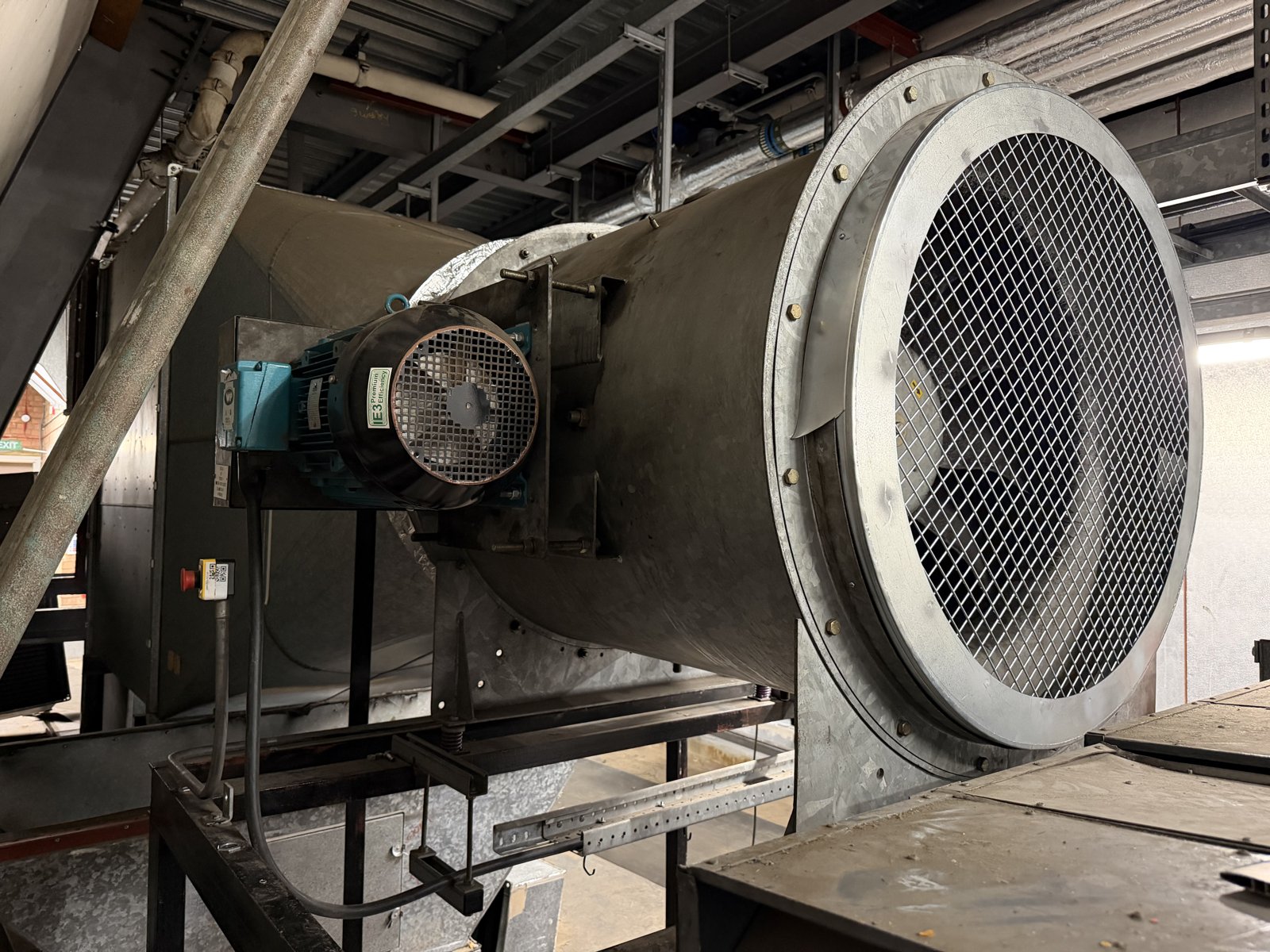
A 15 kW axial extract fan and its Brook Crompton motor, photographed on the callout described in the case study. The assembly had been physically re-orientated during earlier works, which is what prompted the rotation change.
Safety. Everything below involves three-phase low-voltage circuits and, on drive-fed fans, stored DC-bus energy inside the inverter. The work is for competent persons under the Electricity at Work Regulations 1989. Isolate, lock off, prove dead with GS38-compliant test equipment, and observe the drive manufacturer's discharge time before opening any cover. If that is not your job, stop here and call someone whose job it is.
Watch: How three phases make a motor turn
Why does swapping two phases reverse a three-phase motor?
A three-phase induction motor has no polarity. Each supply line carries an alternating voltage displaced by 120 degrees from the other two, and the order in which those three voltages peak — the phase sequence — sets the direction of the magnetic field rotating around the stator. The rotor follows the field. Swap any two lines and the sequence reverses, the field reverses, and so does the shaft. Rotate all three (L1→U, L2→V, L3→W becoming L3→U, L1→V, L2→W) and nothing changes, because the sequence is the same.
The convention is written down. BS EN / IEC 60034-8 (Rotating electrical machines — Terminal markings and direction of rotation) defines the terminal markings U1, V1, W1 and states that when a machine marked to the standard has L1, L2, L3 connected to U, V, W in that order, the shaft turns clockwise viewed from the drive end. Brook Crompton's own installation sheet for the motor on our job says the same thing in one line: “To reverse rotation interchange any two supply leads” (Brook Crompton Installation & Maintenance 103-4E). The manufacturer's connection label inside the terminal box lid repeats it in five languages. There is no competing method.
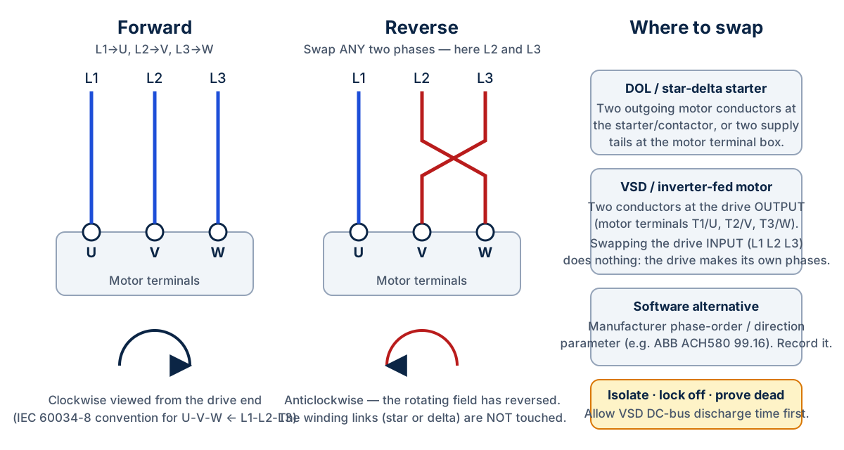
Swapping any two phases reverses the rotating field. The winding links are not part of the operation — they set the voltage configuration, not the direction.
Why is moving the star/delta links the wrong way to reverse a motor?
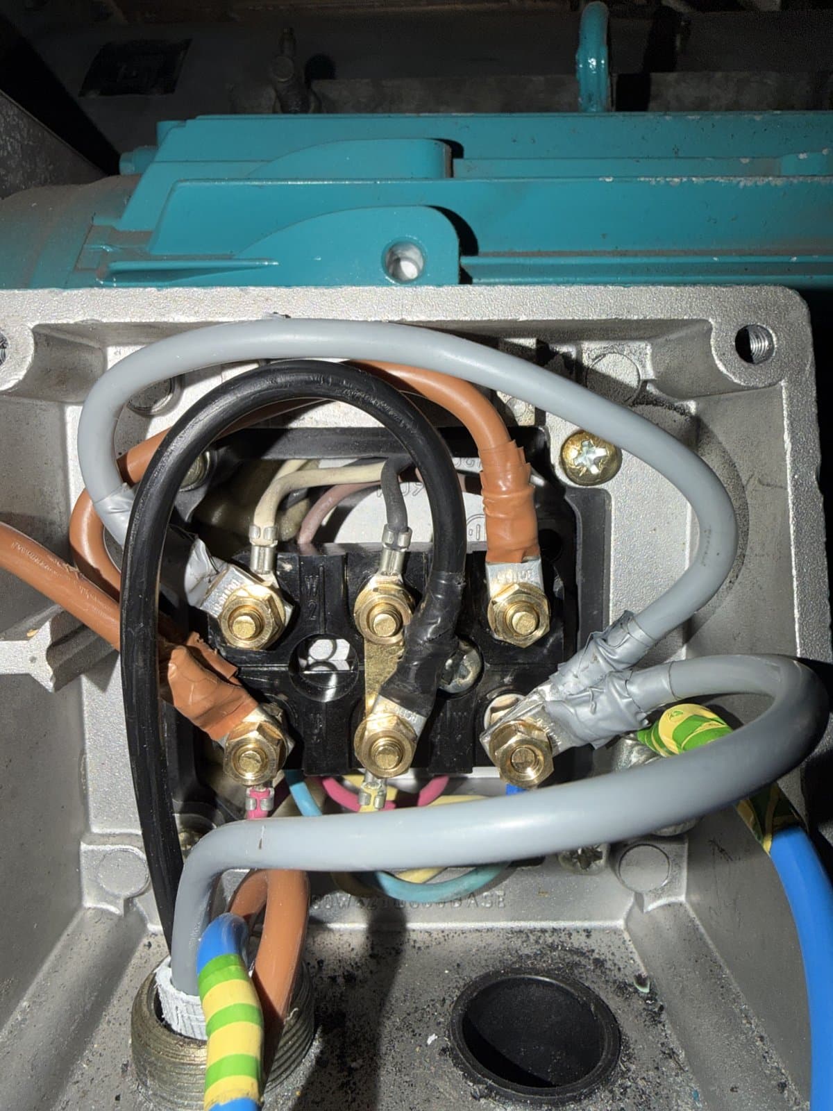
Because the six-terminal links do a different job. On a dual-voltage motor — 400/690 V Δ/Y is the common marking on UK motors of 4 kW and above — the three brass links decide whether the windings are connected in delta for the lower voltage or in star for the higher one. They match the motor to the supply. They have nothing to say about direction, and rearranging them to chase rotation produces one of two outcomes: a motor that is still turning the wrong way, or a winding arrangement the motor was never designed for.
The second outcome is what we found in the case study. The links in the terminal box had been altered, apparently in an attempt to change rotation after the fan assembly had been turned around. The individual windings were healthy — each measured balanced at around 0.5 Ω once separated — but the drive was seeing an abnormal output circuit and tripping Fault 3381, Output phase loss / Missing motor connection on every run command. Restoring the correct delta (W2–U1, U2–V1, V2–W1 on that board) and then swapping two phases at the drive output cleared the fault and gave the required direction, without a new motor or a new drive. If you need the terminal-by-terminal explanation of what those links do, our companion guide to three-phase motor wiring: star, delta and six-terminal connections covers it.
The rule to carry into every terminal box: links set the configuration for the voltage; phase sequence sets the direction. Change the one you actually mean to change.
Where do you swap the phases on a DOL or star-delta starter?
On a direct-on-line (DOL) starter, swap two of the three outgoing conductors at the contactor's load terminals, or two of the supply tails in the motor terminal box. Either works; the panel is usually the tidier place, and it keeps the motor terminal box untouched so the next engineer finds the manufacturer's arrangement intact. Mark the change on the panel drawing.
On a star-delta starter there are six conductors running to the motor, not three, and the starter switches the windings between star and delta itself during the start. Swapping two of those six at the motor end can leave the motor in an incorrect configuration in one or both stages of the start. The correct place to reverse a star-delta-started motor is the incoming supply to the starter — swap two of the three lines feeding the starter, and both the star and delta stages reverse together. Note that a starter-driven star-delta arrangement is a different thing from a motor permanently connected in star or delta by fixed links; the companion wiring guide explains the distinction.
Get a Free BMS Survey
We'll assess your controls and provide a detailed quotation.
How do you reverse a motor on a VSD or inverter?
Three points, in order of how often they trip people up.
First, swapping the drive's incoming phases does nothing. The inverter rectifies the supply to DC and synthesises its own three output phases, so the input sequence is irrelevant to the motor. People do try it.
Second, the hardware method is to swap two conductors at the drive's motor output terminals — on the ABB ACH580 in our photographs they are marked MOTOR T1/U, T2/V, T3/W, next to the INPUT L1, L2, L3 block. That is what we did on the case-study fan, with the drive isolated, proven dead and its DC bus discharged; the drive carries a label requiring a five-minute wait after disconnection for exactly that reason.
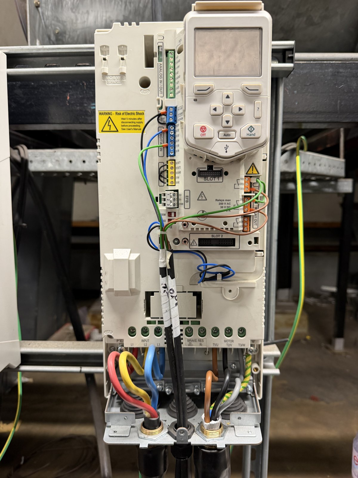
The ACH580 power terminals: INPUT L1 L2 L3 on the left, MOTOR T1/U, T2/V, T3/W on the right. Reversing a drive-fed motor is done on the right-hand block or in software — never on the left.
Third, most modern drives offer a software alternative. ABB's ACH580 HVAC firmware manual (3AXD50000027537) provides parameter 99.16 Motor phase order, with the settings U V W (normal) and U W V (reversed), and describes it as the option for when the motor turns the wrong way and “correcting the cabling is considered impractical”. ABB notes that changing it does not affect the reference polarity — a positive speed reference still means “forward”; the parameter just ensures forward is the correct physical direction. A separate parameter, 20.21 Direction, locks the drive to forward, reverse or request. Other manufacturers have equivalents under different numbers. Two cautions come with the software route: verify the parameter number against the firmware manual for the drive in front of you, and write it down on the panel and in the O&M record. A software reversal is invisible to the next engineer, and a replacement drive commissioned from defaults will run the fan backwards.
Does reversing the fan reverse the airflow?
Not reliably, and this is the part of the job that is more mechanical than electrical.
An axial fan — the type in our photographs, with the impeller in the duct and the motor on the casing — does move air the other way when reversed, but the blades are aerofoil sections designed to work in one direction. Run backwards they still pump, at a substantially lower flow and pressure for the same speed and with poorer efficiency. Some axial impellers are supplied as genuinely reversible designs for smoke-control or bi-directional duties; most general extract fans are not. If a duct arrangement needs the air the other way, the honest answers are a reversible impeller, re-handing the impeller, or turning the fan assembly round and then setting the rotation to suit — which is what had been attempted on the case-study job.
A centrifugal fan does not reverse its airflow at all when the motor is reversed. Air still enters at the inlet eye and leaves at the outlet; the impeller simply throws it at the casing in the wrong direction, flow and pressure collapse, and on a backward-curved impeller the motor can draw more current than it should. A centrifugal AHU supply fan “running backwards” presents as poor airflow, noise and possibly an overload trip, not as air coming out of the intake.
So the sequence on any fan job is: establish which way the shaft should turn (arrow on the fan casing or impeller, manufacturer's data), establish which way the air must go (the design and the BMS sequence it serves), and only then decide what combination of orientation, impeller and phase sequence delivers both. Rotation is one input to airflow, not a substitute for it.
What are the safety rules for changing motor rotation?
The legal frame is the Electricity at Work Regulations 1989. Regulation 12 requires suitable means of cutting off and isolating the supply; Regulation 13 requires adequate precautions to prevent equipment made dead becoming live while work is done on it; Regulation 14 prohibits work on or near live conductors unless it is unreasonable for them to be dead, reasonable to work live, and suitable precautions are taken — a test that changing a motor connection never passes. Regulation 16 requires the people doing the work to be competent. HSE's HSG85 Electricity at work: Safe working practices (third edition, 2013) is the practical guide to isolation, locking off and proving dead; HSE Guidance Note GS38 (fourth edition, 2015) sets the requirements for the test probes, leads and voltage indicators you prove dead with, and expects the indicator to be checked on a proving unit before and after use.
On a drive-fed motor there is a second hazard that a plain contactor circuit does not have. The inverter's DC-bus capacitors hold a lethal charge after the supply is removed. Every drive manual specifies a waiting time — the ACH580 label in our photographs says five minutes — and the motor conductors at the drive output must be treated as live until that time has passed and the bus has been proven discharged. Local isolators at the fan are for the motor circuit, not the drive electronics: if the swap is being made at the drive, the drive's supply is what has to be isolated and locked.
Two further habits are worth keeping. Photograph the terminal arrangement before you touch it, so what you found is on record. And do not use a run attempt as a diagnostic: a drive tripping on a motor-circuit fault is telling you to test the motor circuit, not to reset and try again.
How do you commission and prove the change?
A rotation change is complete when the fan runs in the intended direction, moves air the intended way, draws a sensible current and does all of that in Auto under the control that normally runs it. Brook Crompton's advice is to run the motor briefly to check rotation before coupling it to the load; on a fan that is already built the equivalent is a short bump with the guard in place, watching the impeller, then a longer run with a current reading against the nameplate figure. The 15 kW motor in the case study was returned to service at 40 Hz drawing 15.58 A on the drive keypad against a nameplate 28.3 A at 50 Hz — a single operating point, not a full-load claim, but the kind of reading that belongs in the record.
Then prove the airflow, not just the shaft. Direction at the grille is the minimum; where the fan serves a balanced system, volume should be checked against design using the methods in BSRIA BG 49 Commissioning Air Systems and CIBSE Commissioning Code A, because a fan that has been re-handed or re-orientated may not deliver its previous duty even when it is turning the right way. Finally, hand the fan back to the BMS: put the selector to Auto, confirm the BMS enable and speed reference produce the run, confirm the run and fault status points read back correctly, and clear any alarms raised during the work. If the drive's phase order was changed in software, the parameter and its value go on the panel label and in the O&M. Our note on what goes wrong in BMS commissioning covers the hand-back side in more detail.
Frequently asked questions
Can you reverse a three-phase motor by swapping any two wires?
Yes. Any two of the three supply conductors will do; swapping a different pair produces the same reversal. Swapping all three in rotation does not reverse the motor. On a VSD the swap must be on the drive's output side or in its phase-order parameter, not on the incoming supply.
Why is my AHU fan spinning backwards?
The usual causes are a phase sequence change upstream (a supply alteration, a replacement starter or drive commissioned from defaults, a drive phase-order parameter not carried across), a motor that has been re-terminated after repair, or a fan assembly that was physically turned round. Check the drive or starter connections and any direction parameter before assuming a fault.
Does reversing a centrifugal fan reverse the airflow?
No. Air still enters the inlet and leaves the outlet; flow and pressure drop sharply and the motor may overload. Only an axial fan moves air the other way when reversed, and most axial impellers do so at much reduced performance unless they are a reversible design.
Can I change the direction of a motor by changing the star/delta links?
No. The links connect the windings in star or delta to suit the supply voltage; they do not set direction. Rearranging them to chase rotation can leave the motor in an incorrect configuration — in the case we investigated it caused an ABB ACH580 to trip Fault 3381 output phase loss on every start.
Which ABB ACH580 parameter reverses the motor?
Parameter 99.16 Motor phase order (U V W normal, U W V reversed) reverses the direction in software; 20.21 Direction locks the reference direction. Confirm against the firmware manual for your drive's software version, and record any change on the panel and in the O&M.
Need a fan or drive fault sorted properly?
Alpha Controls works on HVAC controls, electrical services and commissioning across London, Kent and the South East, and fan rotation, motor connection and VSD fault-finding are routine parts of that work. If a fan is running the wrong way, a drive is tripping, or a fan that was “reversed” by someone else is not delivering the air it should, contact the team or request a survey. When the fault is a drive trip rather than a rotation question, start with our AHU fan VSD fault-finding guide.
Sources. BS EN / IEC 60034-8 Rotating electrical machines — Part 8: Terminal markings and direction of rotation. Brook Crompton Installation & Maintenance sheet 103-4E (“To reverse rotation interchange any two supply leads”; run the motor briefly to check rotation before coupling). ABB ACH580 HVAC control program firmware manual 3AXD50000027537, parameters 99.16 Motor phase order and 20.21 Direction, fault 3381 Output phase loss. Electricity at Work Regulations 1989 (SI 1989/635) regulations 12, 13, 14 and 16. HSE HSG85 Electricity at work: Safe working practices (3rd ed., 2013); HSE GS38 Electrical test equipment for use on low voltage electrical systems (4th ed., 2015). BSRIA BG 49 Commissioning Air Systems; CIBSE Commissioning Code A Air distribution systems. Photographs are from the Alpha Controls callout described in the linked case study; the site and client are not identified.
Alpha Controls Team
Specialist BMS installation, commissioning, and maintenance across London and the South East. SafeContractor Approved, BCIA Member.