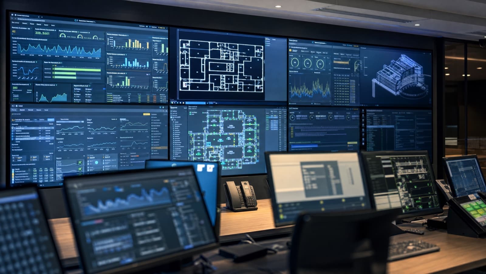

Data centre BMS integration means bringing the mechanical plant (CRAC and CRAH units, chillers, cooling towers, pumps), the electrical plant (UPS, PDUs, generators, transfer switches) and the environmental sensing (temperature, humidity, leak detection) onto one supervisory system with one alarm list. In practice that is three protocol families — BACnet, Modbus and SNMP — a register map for every device, and a test plan that proves the whole thing works when something fails, not just when everything is healthy.
Here is the version of this job nobody puts in the brochure. The mechanical package arrives with CRACs on BACnet, the chillers on a manufacturer gateway, the UPS only talks SNMP to the IT team's monitoring, the power meters are Modbus RTU on a daisy chain that nobody terminated, and the leak detection is a relay contact into a spare input on a panel that was never labelled. Every one of those systems works on its own. None of them work together. The operator has four screens and a spreadsheet, and the first anyone knows about a real problem is when a rack inlet temperature climbs and the tickets start.
It's a common state for an older site to be in: a BMS, an electrical monitoring system, IT monitoring and a ticketing system, none of which talk to each other. It's common. It shouldn't be. This article is about how integration actually gets done in a live UK facility, and where it goes wrong.
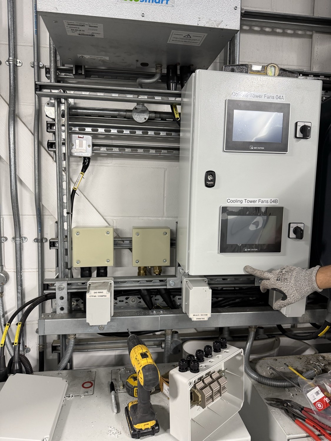
The new cooling-tower control panel at Park Royal. Two cells, eighteen EC fans, one control network back to one panel — installed in a live data centre.
What does a data centre BMS need to talk to?
Four groups of equipment, and they arrive from four different supply chains, which is why integration is a job in its own right rather than a line on the mechanical contractor's programme.
Cooling plant: CRACs, CRAHs, chillers and towers
The cooling side covers CRAC and CRAH units, chillers, dry coolers or cooling towers, chilled-water pumps, and increasingly coolant distribution units (CDUs) for direct-to-chip liquid cooling. Almost all of this is BACnet now — either BACnet/IP over the OT network or BACnet MS/TP over RS-485. The standard is ASHRAE 135, adopted in the UK as BS EN ISO 16484-5, and it defines the object types (analogue input, binary output and so on) that let a Trend, Distech, Siemens or Schneider head end read a Vertiv or Stulz CRAC without a custom driver.
Electrical plant: UPS, PDUs, generators and transfer switches
The electrical side covers UPS systems, PDUs, generators, automatic transfer switches and switchgear. This is where BACnet stops being the default. UPS and PDU manufacturers grew up in the IT world, so their native language is SNMP — the same protocol the network team uses to monitor switches. Larger units offer Modbus TCP as well, usually via an optional network card. Generators and ATS controllers are almost always Modbus.
Metering and the PUE figure
Power meters sit at the incomer, on each UPS output, on each PDU and often per row. Modbus RTU on RS-485 is still the norm because it's cheap and the meters are in switchboards, not on the network. A good data centre BMS is also the source of the PUE calculation, and the definition matters: ISO/IEC 30134-2 (mirrored in Europe as EN 50600-4-2) defines PUE as total facility energy divided by IT equipment energy over a full year, so the meters feeding that ratio have to be in the right places and reading correctly.
Environmental sensing and leak detection
This covers rack inlet temperature and humidity, underfloor and in-row sensors, and leak detection under raised floors and around CRAC condensate lines. It is BMS-native territory — hard-wired inputs or BACnet sensor networks — and it's the part that gets neglected because it isn't “equipment”. Our data centre leak detection guide covers the sensing side in detail.
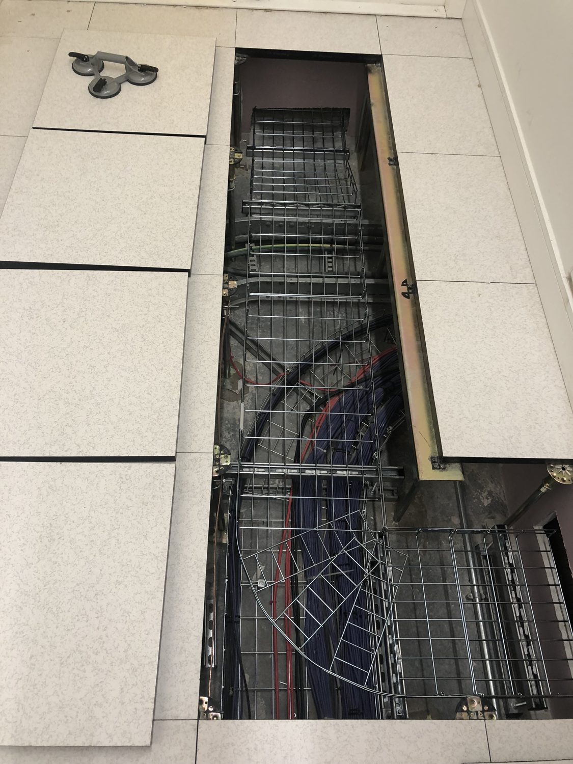
Floor tiles up on a data centre raised floor. The basket tray and cable routes in the void are where BMS sensor, network and power cabling has to find its own segregated path.
Which protocols does a data centre BMS use, and where do the joins fail?
A realistic UK data centre BMS talks three languages at once, and the integration contractor's first job is to write down which device speaks which.
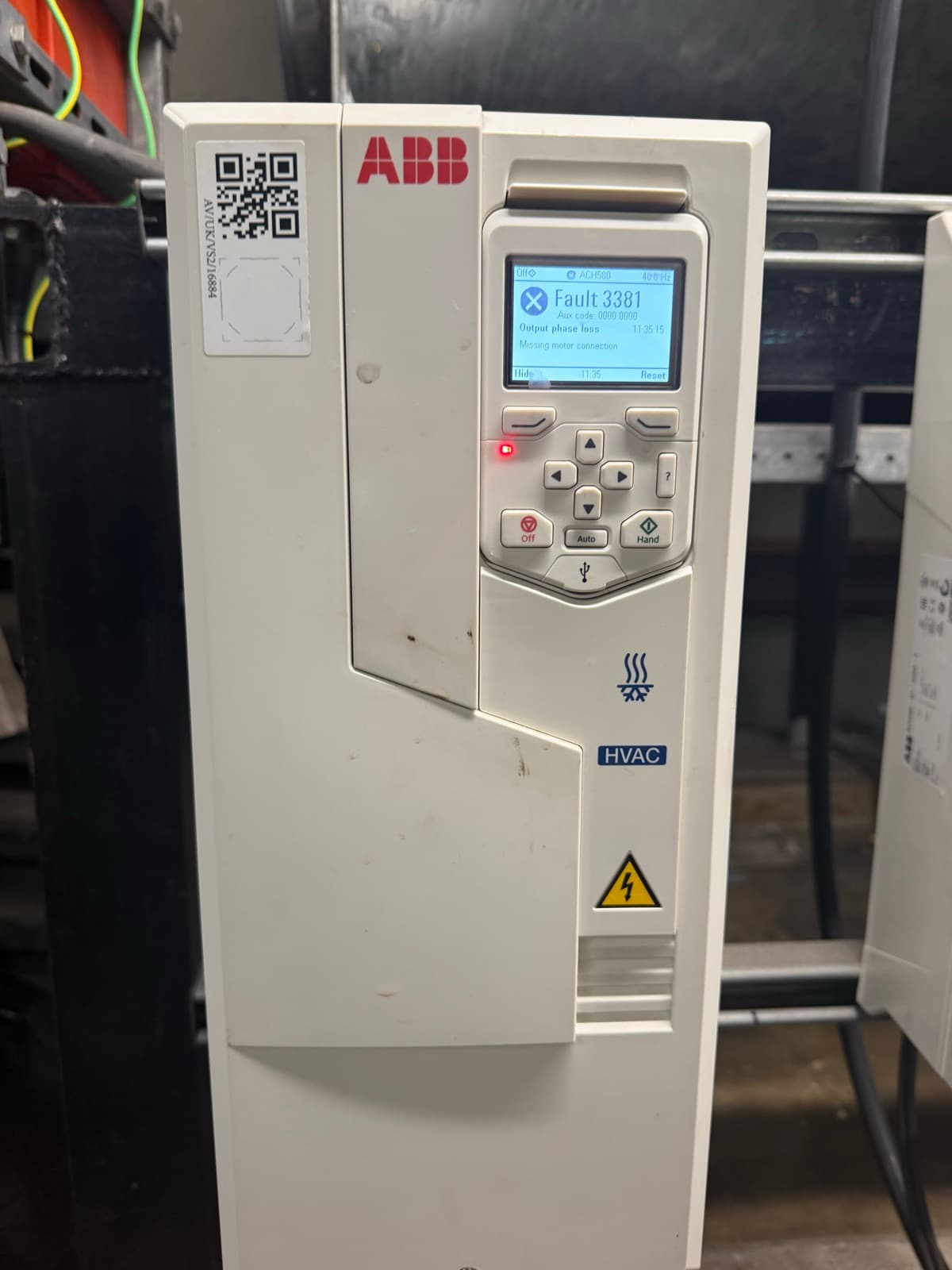
BACnet/IP runs over UDP port 47808 on the OT network and is the backbone for mechanical plant. BACnet MS/TP is the serial version for field devices on RS-485. Modbus TCP runs on port 502 and Modbus RTU on RS-485; both are register-based, which means every single point has to be looked up in the manufacturer's register map and typed into the controller by hand, including the data type and scaling. SNMP (v2c or, properly, v3 with authentication) is how UPS and PDU network cards expose their status through MIB files. Some head ends read SNMP natively. Many don't, and you end up with a protocol gateway in between — one more device to configure, power, back up and document.
A common question on data centre projects is which protocol the site actually runs on. The honest answer is boring: all of them, and the trouble starts at the joins. A Modbus register read with the wrong byte order gives you a plausible-looking number that is completely wrong. An SNMP trap that isn't acknowledged gets sent once and lost. A BACnet device with a duplicate instance number silently fights with its twin. None of these show up as a fault. They show up as data you can't trust.
For the protocol fundamentals, our BACnet vs Modbus guide covers the differences; this article is about what happens when you have to run both alongside SNMP in a room that can't be switched off.
Why is BMS integration in a data centre harder than in an office?
Because you can't turn anything off to test it, and because the tolerances are tighter than any commercial building.
ASHRAE TC 9.9's Thermal Guidelines for Data Processing Environments sets the recommended server inlet envelope at 18–27°C, with the allowable A1 envelope at 15–32°C and A2 at 10–35°C. An office BMS that lets a floor drift by two degrees for twenty minutes generates a complaint. A data centre BMS that lets a cold aisle drift the same amount is eating into a warranty envelope and, if the drift continues, into hardware. That is the environment the integration is being tested in.
On the European side, BS EN 50600-2-3:2019 sets the environmental-control requirements for each data centre space and ties the design of the environmental-control system to four availability classes (1 to 4) defined in EN 50600-1. It also sets granularity levels for measuring the energy used by the environmental-control system itself. PUE is defined separately, in ISO/IEC 30134-2, and its measurement category depends on where the IT energy is metered. If the BMS integration doesn't put meters in the right places, your PUE figure is an estimate, not a measurement.
And then there's the operational reality. The Uptime Institute's Annual Outage Analysis 2025, drawing on its 2024 survey, found that 53% of operators had an outage in the previous three years, and that among impactful outages, power was the primary cause for 54% of operators and cooling for 13%. The 2026 edition still names power as the leading cause. Those are the two systems the BMS integration is supposed to be watching. If the integration is half-finished, the BMS is watching neither properly.
Get a Free BMS Survey
We'll assess your controls and provide a detailed quotation.
Where do data centre BMS integrations usually fail?
The same faults turn up again and again, and none of them are exotic.
The UPS was never on the BMS
The IT team monitor it by SNMP and the BMS head end was never given a route to it, or nobody bought the Modbus card. So the facilities team have no UPS alarms, no battery status and no load figure on the same screen as the cooling that keeps the batteries alive. It is an easy gap to leave, because each system works on its own.
The Modbus register map was guessed
Someone mapped the CRAC's Modbus points from a different model's manual. Supply temperature reads fine because it was in the same register. Compressor status reads a different bit. The point is “working” on the graphic and wrong in reality, and it's only found during an alarm review months later.
The RS-485 trunk was never terminated
The trunk was daisy-chained through six switchboards with no termination and no biasing. Meters drop off intermittently. The integrator's log shows retries; the graphic shows stale values with no stale indication. The energy report is quietly wrong. We wrote up the wiring side of this in the protocol guide, and it's the same lesson every time: RS-485 is unforgiving of shortcuts.
Power and control wiring share containment
Fan power and fan network on the same tray, drives radiating into the comms cable, intermittent BACnet errors that nobody can reproduce. Two different rules apply here. BS 7671 Regulation 528.1 is the safety rule: it doesn't allow Band I (extra-low voltage control and data) and Band II (230/400 V) circuits in the same wiring system unless every cable is insulated for the highest voltage present or the bands are physically partitioned. Interference is a separate question, covered by BS 7671 Section 444 on electromagnetic disturbances and the power-to-data separation distances in BS EN 50174-2. In a data centre we keep power and control on separate trays end to end, because a noisy control network in a critical facility is a fault you'll chase for years.
Nobody tested what happens when something fails
The integration was signed off with everything running. Nobody dropped the utility supply, nobody failed a chiller, nobody unplugged the BACnet router to see what the CRACs did when they lost the head end. The first time the system experienced a real failure was in service.
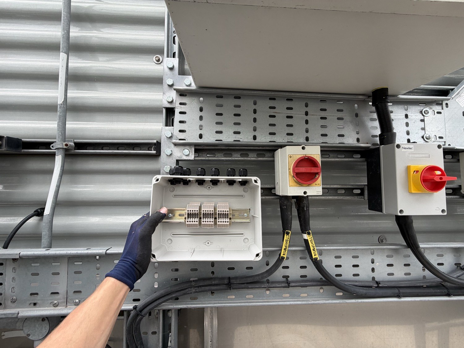
Rooftop network enclosure at Park Royal with the fan networks on their own containment, separate from the power. Boring, deliberate, and the reason the network stays clean.
What standards apply to data centre BMS integration?
Three matter on every job, and a fourth if the site is Tier-certified.
BS EN 50600-2-3:2019 (environmental control) sets the requirements for temperature, humidity, airflow and liquid-spill protection by space, tied to availability class, and specifies energy-monitoring point locations. BS EN 50600-3-1 (management and operational information) specifies the operational processes and, crucially for integration, the information that must be handed over to operations on completion of a new build and what is required to accept the facility into service. Your BMS points schedule, protocol map and alarm philosophy are part of that handover, not an afterthought.
IEC 62443 applies because the BMS is an OT network sitting next to the IT network. It requires the system to be divided into zones with defined conduits between them, and it's why we won't put a BMS controller on the same VLAN as the corporate network or leave a protocol gateway with default credentials. The NCSC Cyber Assessment Framework says the same thing in UK terms. Our BMS cybersecurity article covers the practical side.
If the facility is Uptime Tier III (concurrently maintainable) or Tier IV (fault tolerant), the BMS integration has to respect that topology. A Tier III site can take any component out of service for maintenance without affecting the load; the BMS network and the controllers it depends on must be maintainable the same way. One BACnet router as a single point of failure in a Tier III facility is an integration defect, whatever the graphics look like.
Park Royal: replacing cooling-tower fan control in a live data centre
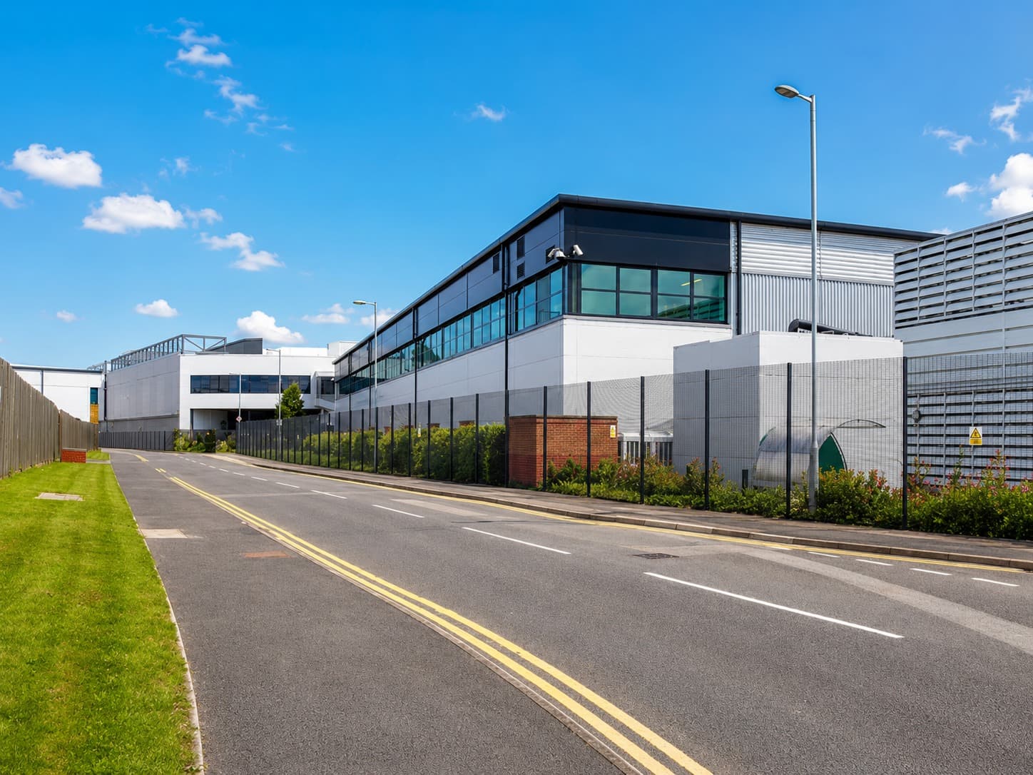
Our Park Royal data centre project is a good example of integration in a live site, because the plant couldn't stop while we worked.
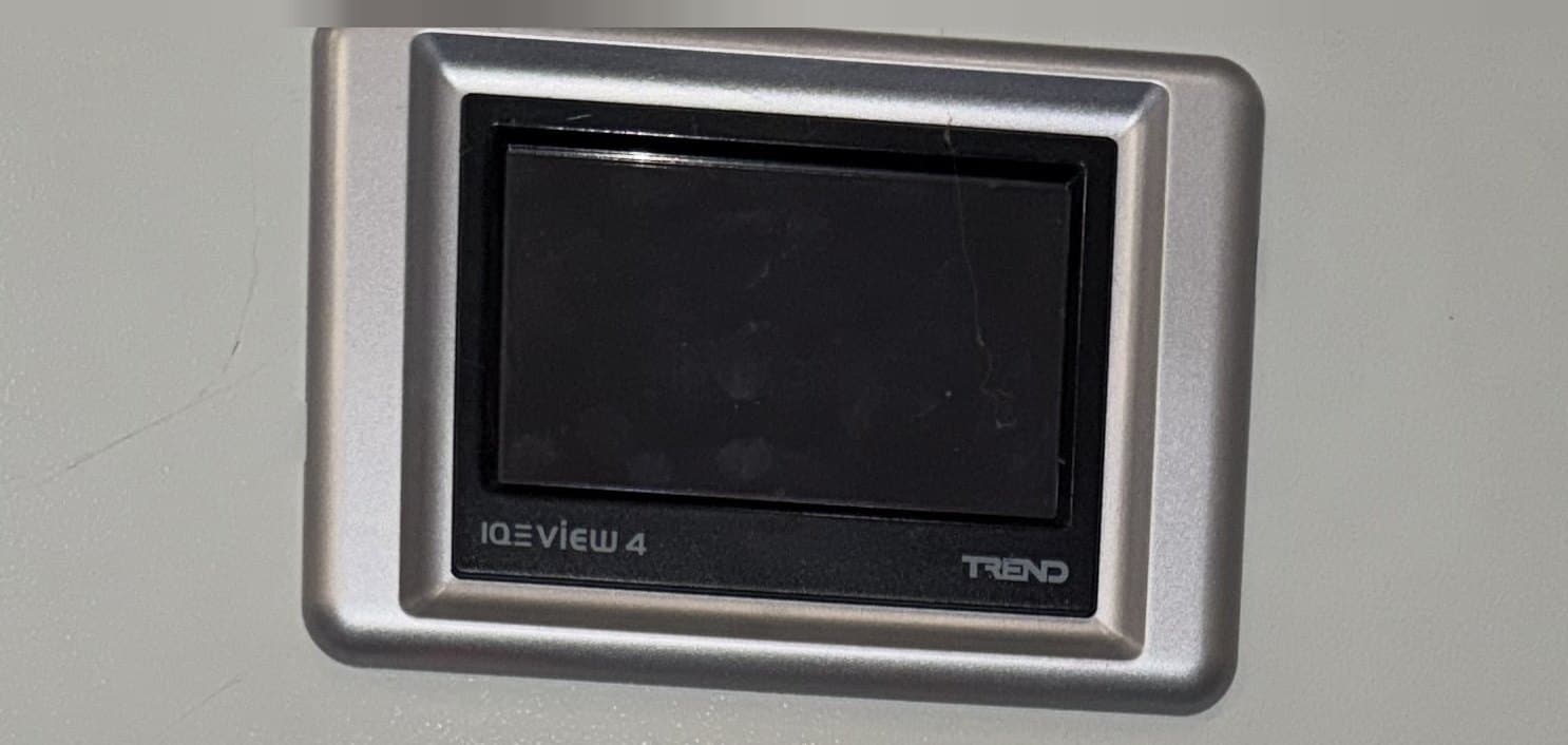
The rooftop cooling tower had two cells, each served by one large fan on its own inverter, driven from a panel at Level 1. The two fans were replaced by eighteen electronically commutated (EC) fans — nine per cell — each individually powered and individually networked. The two inverters came out. A new BMS control panel went in at plant-room level, with an on-panel touchscreen supervisor, and a control network backbone was run from Level 1 up to Level 3 to a pair of enclosures either side of the tower.
The integration decisions were the job. Power was distributed through a GRP distribution board on each side of the tower; the fan networks landed in separate adaptable enclosures; power and network ran on fully segregated containment across the roof. A single network link was routed over the roof between the two sides so that all eighteen fans sit on one control network back to one panel. Splitting the duty across a bank of individually controlled fans gives finer control of cooling output and keeps the tower running if an individual fan is taken offline.
The works were delivered in a live, business-critical data centre, with final testing and commissioning as the closing stage. As a general method for this kind of job, new panels and containment go in alongside the existing arrangement, networks are proved end to end before plant is connected to them, and the changeover is staged so the plant keeps carrying its duty. Most of the effort in a critical environment goes into keeping the plant running while the control changes underneath it.
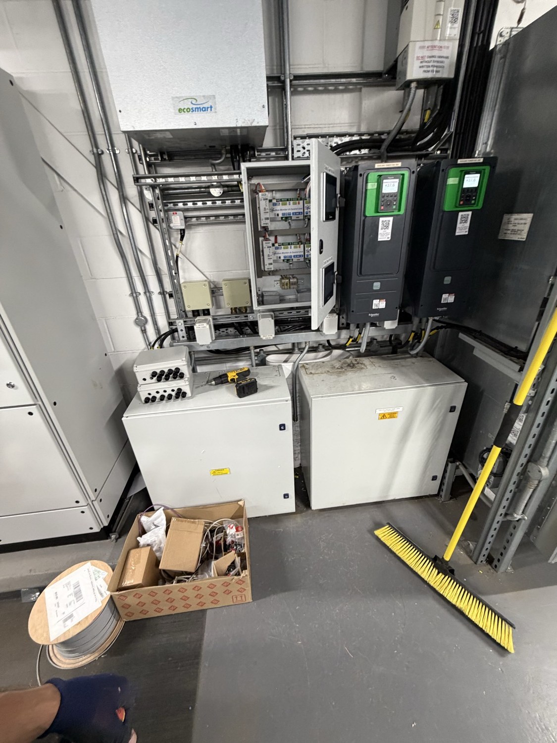
Plant room at Level 1 during the works. The new control enclosure is open for wiring beside the existing drives; the site kept running throughout.
What does a well-integrated data centre BMS look like?
It looks like a points schedule that matches reality, a protocol map someone can hand to the next contractor, and a test record that proves what happens when things break.
Every device is listed with its protocol, address, register or object map, and the physical route its network takes. Every point on the graphic has been point-to-point tested against the physical device, not against the manufacturer's manual. Every UPS, PDU and generator is on the same alarm list as the CRACs, with the alarm priorities worked out in advance rather than left at manufacturer defaults — we've written that up separately in data centre BMS alarm management. The BMS network is on its own VLAN, segmented per IEC 62443, with no single router the whole facility depends on.
And the integrated systems test (IST) has actually been done. That means dropping the utility, watching the generators and ATS pick up, watching the UPS ride through, watching the chillers restart in the right order and the CRACs recover — with the BMS logging every step and every alarm arriving where it should, at the priority it should. If the IST hasn't been run with the BMS as a witness, the integration isn't finished.
When should you review your data centre BMS integration?
Three triggers. First, any time equipment changes — a new UPS, replacement CRACs, a liquid-cooling CDU — because the new kit almost never arrives speaking the same protocol as the old. Second, when the facilities team are working from more than one screen to understand the site: that is the symptom of an integration that stopped halfway. Third, before an Uptime or EN 50600 assessment, because the assessor will ask for the monitoring evidence and a half-integrated BMS can't produce it.
If you inherited the site, add a fourth: as soon as you can. The gaps in an inherited integration are the ones nobody knows about until a real fault finds them. Our legacy BMS upgrade guide covers how we approach the retrofit-or-replace decision on older systems.
Getting data centre BMS integration right
Integration is protocol work, wiring work and test work in equal parts, done in a room that can't be switched off. It's the part of a data centre controls project that decides whether the BMS is an operations tool or a wall of graphics. Alpha Controls integrate plant onto Trend, Distech, Siemens and Schneider systems across London and the South East, and we've delivered controls work in a live data centre at Park Royal. If you've got a site where the systems don't talk to each other, or a project where they need to from day one, talk to us or request a quote.
Alpha Controls Team
Specialist BMS installation, commissioning, and maintenance across London and the South East. SafeContractor Approved, BCIA Member.